Continue to Site

Welcome to EDAboard.com

Welcome to our site! EDAboard.com is an international Electronics Discussion Forum focused on EDA software, circuits, schematics, books, theory, papers, asic, pld, 8051, DSP, Network, RF, Analog Design, PCB, Service Manuals... and a whole lot more! To participate you need to register. Registration is free. Click here to register now.

555 timer as PWM controller

Status
Not open for further replies.

saurav_sdpl

Full Member level 3
Joined
Sep 29, 2006
Messages
185
Helped
4
Reputation
8
Reaction score
2
Trophy points
1,298
Activity points
2,522
hii,

I have to design a flyback smps of o/p power 3W.

I want to use 555 timer as PWM oscillator and control the duty cycle from 0 to 50% using control voltage.

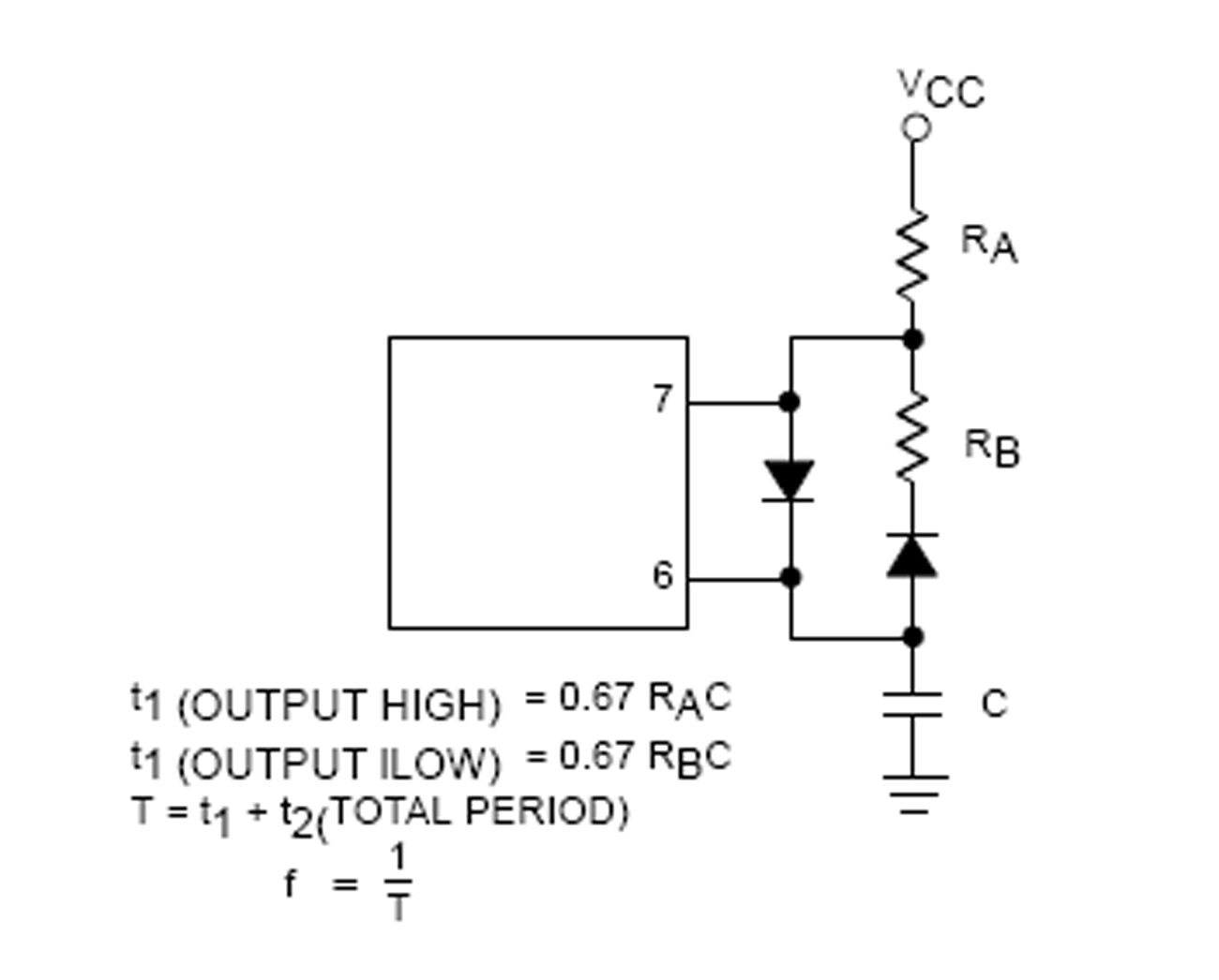
1. In what configuration 555 timer will be configured, whether astable or monostable mode

2. How can i limit the duty cycle upto exact 50%

3. How do i calculate the frequency of operation

4. and what other design points i need to take care

Its urgent
 

Is the 555 really that much cheaper than a voltage mode
PWM (35xx series)? At least you'd have things like a voltage
reference and the ability to drive a power MOSFET decently.
Some versions have a 50% max duty, built in.

Why you "want" to use the 555, I don't know. There are so
many options out there that are all pretty cheap.
 

Dear Saurav_sdpl, we have done 555 control of boost and buck circuits for auxiliiary power supplies up to 50W - they work well.
Regards, Orson Cart.
 
[Actually i tried to experiment to vary the duty cycle of 555 timer using the control pin, but i am not able to vary the duty cycle below 50%. Also when i keep the control voltage below 1V. I get a distorted wave shape at o/p.

Please suggest the reason for the same.
I have attached the schematic
 

Attachments

  • Simulation file.doc
    163.5 KB · Views: 159

555's can be made to work below 50%. A common way to do that is to insert diodes to separate the charge and discharging resistors. AN170 from Philips has a nice discussion of that, but appears not to be available any longer. Here is a portion of Figure 9 from that application note.


Since AN170 is not longer available, I will attach it here too.

John

Edit: Forgot to add that I agree with dick_freebird's analysis above (Post #4).
 

Attachments

  • 555AN.pdf
    378.7 KB · Views: 140
Last edited:

This is OK , but please have a look at the circuit i have attached in the word file.

I want to get a PWM wave with a duty cycle from 0% to 50% max by varing the voltage at control pin.(2V-4V)

What are the design equation should i follow to achieve this
 

sorry , you are wasting your time and money.

UC3845 or ucc38c45 has 0 to 50% duty cycle and has on-chip driver etc etc.

So do many others.

UC3845 cheaper then 555 timer.

also is NCP12XX range
 

[Actually i tried to experiment to vary the duty cycle of 555 timer using the control pin, but i am not able to vary the duty cycle below 50%. Also when i keep the control voltage below 1V. I get a distorted wave shape at o/p.

Please suggest the reason for the same.
I have attached the schematic

The 555 will naturally run from 50% to about 100% duty cycle. All you have to do is invert the the 555 output to get about 0% to 50% duty cycle.

You may have to change your control signal around to work with that.
 

Status
Not open for further replies.

Similar threads

Part and Inventory Search

Welcome to EDABoard.com

Sponsor

Back
Top