boylesg
Advanced Member level 4
- Joined
- Jul 15, 2012
- Messages
- 1,023
- Helped
- 5
- Reputation
- 10
- Reaction score
- 6
- Trophy points
- 1,318
- Location
- Epping, Victoria, Australia
- Activity points
- 11,697
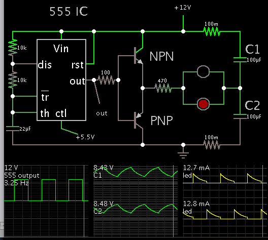
How do you get this sort of circuit to work?

I don't understand what I am doing wrong.
A complementary pair like this works perfectly well as part of a class AB amplifier but there seems to be no way to make it work from 555.
It appears that the 555 cannot switch the BCs on enough for them to generate or sink enough current from their emitters.
I have had this sort of problem before with a Jacob's Ladder kit, from Jaycar, that simply did not work once soldered. It also was driving a single BC327 which in turn drove a automotive power darlington.
- - - Updated - - -
It works just as well without the diodes, but I can only get it to output enough current to drive a LED directly, both to GND and from Vcc.
But what I don't understand is why it seems impossible to get enough current out of the totem pole to light up an automotive light bulb....even dimly.