Continue to Site

Welcome to EDAboard.com

Welcome to our site! EDAboard.com is an international Electronics Discussion Forum focused on EDA software, circuits, schematics, books, theory, papers, asic, pld, 8051, DSP, Network, RF, Analog Design, PCB, Service Manuals... and a whole lot more! To participate you need to register. Registration is free. Click here to register now.

50V Discharge Magnetizer issues

Status
Not open for further replies.
The pulse power absorbed by the transistor may exceeed it's safe operation area.
 

The fact that the transistor apparently survives some pulse events reveals that the circuit has considerable non-ideal elements, particularly capacitor ESR and inductor series resistance. Otherwise, the stored capacitor energy would be quantitatively transferred to the transistor during about 200 µs and reliably destroy it in a single shot.

The obvious question is: What makes you think that the transistor can stand the pulse energy? Have you calculations indicating safe operation?

Flyback diode parameters won't be a problem unless you try to switch-off the transistor during the kA pulse.
 
  • Like
Reactions: mag5

    mag5

    Points: 2
    Helpful Answer Positive Rating
Hi,

there may be some posibilities:

I don´t think it is an overcurrent problem causing overheat of the FET.
The current should be limited to 25A (50V, 2Ohms). With the 4.5mOhms max and a duty cycle of 50/10000 the dissipated power should be negligible 14mW averaged, 2.8W peak. All this is safe.

So i rather think it is a overvoltage problem.
The FET is rated with 75V, that is not much headroom for a 50V system.
(You can use it with a proper low impedance pcb layout and fast and well chosen protection devices, but don´t use it in a breadborad design)

********

D2 only protects against stored energy in L1.
It does not protect against overvoltage caused by series inductance in power supply, stray inductance, shunt inductance and most of all A1.

Simplest test: connect a TVS (across D and S, as short wires as possible) of the FET. It shoud be rated to withstand 50V DC and limit voltage to max. 75V at 25A.
Additionally i´d consider to use a FET with higher voltage rating. (max. 100mOhms and 60W peak power rated SOA, average power is 0.3W, but use one with 200V or higher)


Good luck

Klaus
 
  • Like
Reactions: mag5

    mag5

    Points: 2
    Helpful Answer Positive Rating
The current should be limited to 25A (50V, 2Ohms). With the 4.5mOhms max and a duty cycle of 50/10000 the dissipated power should be negligible 14mW averaged, 2.8W peak. All this is safe.

You possibly misread the schematic (or did I?). I see the capacitor discharged through about 5 mOhm (Rdson + 1 mOhm shunt) in series with 2 µH. Results in about 2 kA peak current.
 

Hi,

You possibly misread the schematic (or did I?).

Yes, my mistake.
I really didn´t read the capacitor value in uF but in pF.
Thanks for correcting me.

**********
Now new calculations:
max. voltage in capacitor is 50V. Stored energy is 33Ws.
33Ws every 10 seconds make an average power of 3.3W. No problem

**********

If the 33Ws are completely (without loss) transfered to the inductor the peak current is about 5700A. This is the maximum possible even with zero ohmic resistance.

With the resistance (ignoring the inductance) the current peak may be 2kA.
To be even more realistic one should take inductance copper resistance into account, too.

My estimation is that the current will never exceed 500A because of disspated energy in resistors. (500A for 100uS should be OK for that big FET, or not?)
Maybe there is somebody who could do a simulation about this. Also interesting for me...

Klaus
 
  • Like
Reactions: mag5

    mag5

    Points: 2
    Helpful Answer Positive Rating
The ideal current waveform looks like this (for Rdson = 4 mOhm), but there are most likely additional series resistrs in the real circuit. The total capacitor energy 0.5 C U² is about 8.5 W and considerably beyond the transistor pulse handling. I however don't see a purpose of guessing further without an estimation of other series resistors.

 
  • Like
Reactions: mag5

    mag5

    Points: 2
    Helpful Answer Positive Rating
Δ
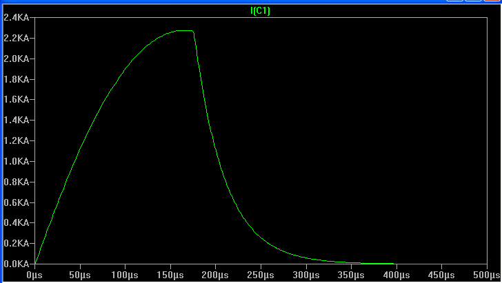
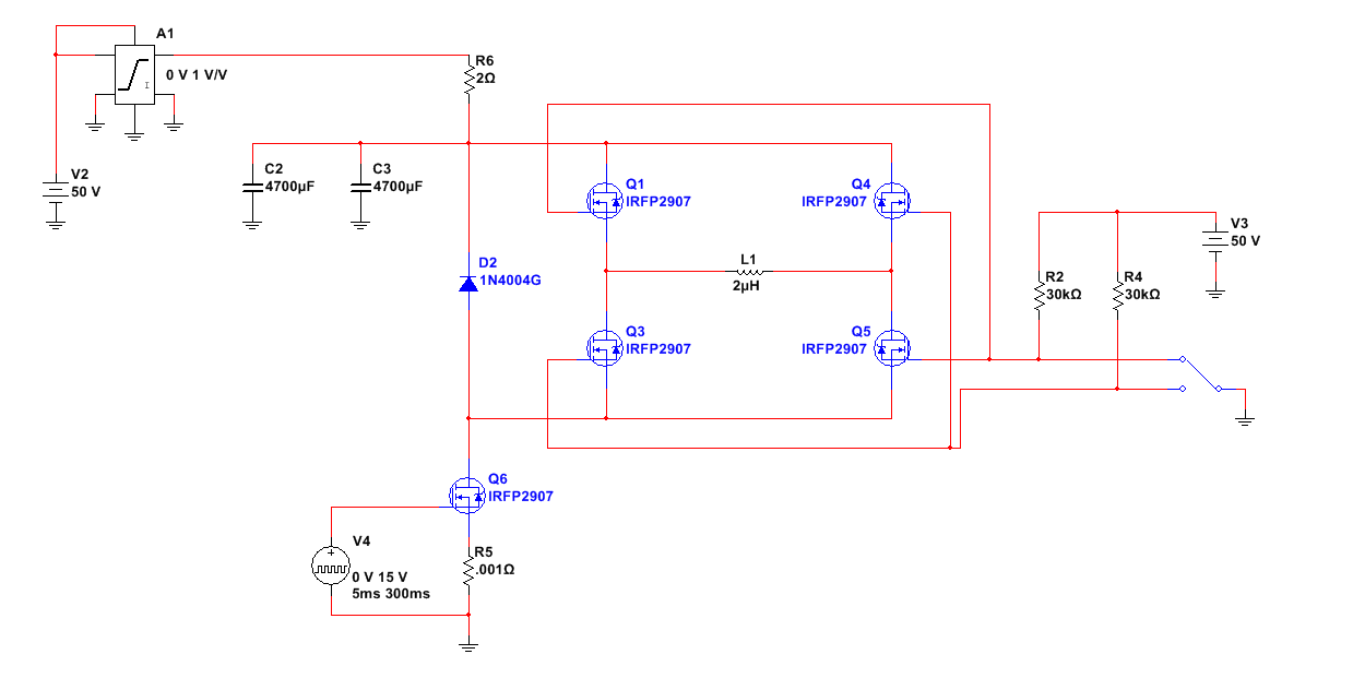
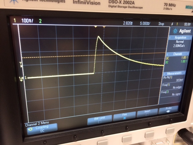
Heres a simplified circuit, that inconsistently blows the mosfet. Charging the cap with a 50V 2A limited supply, and firing 5ms pulses at a period of 10s. I sense the current at the 0.001mOhm shunt. What am I doing wrong?

https://obrazki.elektroda.pl/4241127500_1410385744.png
Basic inductor current V=LΔI/Δt
The Inductor value or pulse duration seems wrong and C ESR is unstated but if smaller than MOSFET is the worst case.

with ΔI=50/2u*5m=500kA for a device with a package limitation of 90A. ( see footnote 6 page 2. )
Although the RdsOn would limit the current to 50V/4.5mΩ or 10kA.
The 2 Ohm 6600uF time constant is 0.0132 second,

EDIT: The package limitation of 90A in fine print is the reason the MOSFETs are failing. ( I^2t fuse link on wirebond )
NO cap. can handle this ripple current.
change L to prevent burning MOSFET

What is this circuit trying to do?
 
  • Like
Reactions: mag5

    mag5

    Points: 2
    Helpful Answer Positive Rating
Hi,

today is not my day... :sad:, better relax some hours..

FvM´s calculations are right.

Klaus
 

Thank you all for the discussion so far. Here are some updates:

The capacitor bank actually is 9400uF from a pair of parallel 4700uF capacitors, low ESR **broken link removed**

I use an H-bridge with the same mosfets to control the load polarity.

The series resistance from Q6 and R5 is below 0.00 Ohms, the lowest I can measure. It is a 4-inch trace that is 150mil wide and 2oz copper thickness.

My design has multiple channels of this circuit driving a fixture with six loads surrounding a balanced armature receiver. I am attempting to create various flux gradients in order to move the receiver reed. This is done by varying the charge levels and pulse width between channels.

Essentially I am trying to create six channels of this where each channel can dump at least 500-1000A. I cannot change my coils, the fixture is already designed and built by another person.


Unfortunately, I am not an expert in power electronics- I am an audio designer.
Is this topology generally wrong for my application, or can I find a mosfet with correct specs? The range of options in the HEXFET family is large.


Here's a little more detail-


Some interesting new details in your post. The absorbed energy per transistor is considerably reduced by having effectively three transistor in series circuit. The inductors series resistance is still unknown. If it's low, the maximum energy per transistor may be still exceeded.

There's however a dramatical new issue revealed in your schematic (presumed it's correct). By sending 50 V to the transistor gates, your exceeding the maximum gate voltage rating beyond any reasonable limits. That's a sufficient condiction to destroy MOSFETs. At the same time, the high side transistors aren't fully turned on.
 
  • Like
Reactions: mag5

    mag5

    Points: 2
    Helpful Answer Positive Rating
Yes Vgs max =+/- 20V so change it to V3=15V

I figured the 4" x 150 mil 2oz track is 0.6 mΩ
Each cap is 25mΩ @10kHz

SRF is not given for the caps by Vishay ( but may be measured easily) and is likely to be < 100kHz, so it will look inductive above this.

So I would choose some expensive Polypropylene (PP), Metallized Caps to lower the ESR above SRF. ( self resonant frequency) such as these

To check energy , E[Joules] = I²R*t for C~10mF, R=2 , τ=20ms for an exponential decay the total energy is 50% of what it would be if the current was constant for the duration τ=RC.
Thus to achieve 1000A total loop ESR @50V must be 50V/1000A = 50mΩ


For peak current Ip with an exponential decayed current becomes E=½Ip²R*t

For Ip= 1000A and τ=20ms and ESR = 50mΩ

E = ½ 10e6 * 50x10e-3 * 20x10e-3 = 500 J This is a big load. The IRFP2907 absolute maximum 1.97 J, so you would need 250 perfectly matched MOSFETs

Thus you have been using the MOSFET's RdsOn as fuses ( also excess Vgs )

This must be pretty low ESR special motor. What is the coil resistance? What is the Tesla level? Does the core saturate? Steel laminated Core can handle 1.5 to 2T typ.

With RdsOn <4.5mΩ and with the 2 caps at 25/2 mΩ and the requirement for a loop ESR of 50 mΩ I would use 50-12.5-4.5= 33mΩ non-inductive power resistor. This can be 8ft of 16 AWG wire folded in half and twisted to use the leads at one end to achieve this resistance and null inductance. It has a fuse capability of 2kA for 32ms.

If this doesn't appeal to you and you still want 1000Apk reduce the ESR of Caps and MOSFET to 5mΩ total and use 45mΩ of series non-inductive wire which now will consume 90% of the 500 Joule energy. So you may only need 5 to 10 MOSFETs in parallel. kewl Tesla only has 88.

EDIT as an addendum. Your 4" wire trace is inadequate and should be bridged with 3mm flat braided wire to support the 1000A.

I'm sure there will be other issues.
 
  • Like
Reactions: mag5

    mag5

    Points: 2
    Helpful Answer Positive Rating
Yes Vgs max =+/- 20V so change it to V3=15V

The circuit either needs separate (floating) high side gate supply, or a clamp circuit that limits Vgs of each transistor to a safe limit. In this case,V3 should be increased to a value that switches the high side transistors fully on.

Secondly, I think you can skip the E=I²R*t calculation. In the present circuit, the total pulse energy is limited by the stored capacitor energy. It's shared between capacitor ESR, transistors and load resistance.

The actual current waveform isn't exponential because the circuit is of the RLC type. See my previous post for a typical shape.
 
  • Like
Reactions: mag5

    mag5

    Points: 2
    Helpful Answer Positive Rating
Well the schematic without ESR's in each component simplifies the picture but causes misunderstandings in operation.

I agree Cap storage energy is the limit. E=½CU² which in fact is the same as exponential decay E=½Ip²R*t . My fault for using the charge time constant RC=2 *0.01F = 20ms instead of the discharge time constant for 1000A, T=0.05Ω*0.01F = 500us. This raises an electromechanical question. Does the OP know if a motion is possible on the balanced armature motor in this short duration?

I wonder what the real end-use of this moving reed is? I can't help to think there must be better ways to do it. This is get up to MRI and XRay type levels of interference or a trigger for a bomb :roll:

The only resonance is 500 Hz resonance, long after the 500us discharge, when the low side switch opens up, which gives rise to a big transient that triggers ringing limited by the Zener clamp voltage. The motor coil current limit of 50V/2R = 25A steady state stored energy E=½LI² +3125 uJ after the discharge is small but high voltage.

Rather than analyze this design which fails, and trying to patch it., wouldn't it be better to define the elector-mechanical goal, show the model and then the waveforms required and then do the design ?? Specs please.
 
  • Like
Reactions: mag5

    mag5

    Points: 2
    Helpful Answer Positive Rating
Thank you all for the good information. I came into this project with the fixture, coils, and initial circuit already built. I just checked the existing build, and the capacitor bank is actually two parallel 47000uF caps (C2 and C3). WOW.
I also measured each coil and they are 15uH. Also, yes the Vgs of the H-bridge mosfets is wrong.

The requirement for the system is for each channel to create flux density of up to 0.8T, which was modeled (an ideal source in comsol) with 800Apk through the load. The gate pulse at Q6 will be increased to 100ms. As mentioned, I’m not sure if my present system is the idea way to accomplish this. I am, however, stuck with using my fixture of six coils.

L1 ESR = 0.091Ω
C2 ESR = 0.175Ω
C3 ESR = 0.168Ω

Interestingly, of the six channels, two actually fire consistently and I have seen a peak current of up to 1200A (unless my DAQ is incorrect). The others eventually blow out. Using 2 opposing fields, the reed is able to be moved. The units are in pairs, and if I can center both simultaneously this optimizes their performance immediately.

Like I said before, I am an audio guy so this is beyond my typical range, thank you for the help. When I’m done I can go back to measuring mV systems and stop blowing up transistors.


Try some basic Electronics

Current produces an electromagnetic force in the coil. The force produces acceleration on a mass. The velocity is the integral of time over this pulse and position is the second integral of time.

Changing your gate time in milliseconds does nothing to extend the Capacitor discharge current duration when it discharges in a microsecond.

EDIT (corrections)
Reviewing your latest parameters, the total ESR in LC is 0.175//0.168 +0.091 = 0.263 with C1//C2=0.094uF the RC time constant is 0.025s, while the L/R time constant is 10u/0.263 =38 us , The stored Cap energy E=½CU² =118J but for 20ms and Ip=190A, the stored energy in the inductor is E=½LIp²*t= 95 Joules so that means 80% of the energy is used in capacitor which is not fully discharged.

95J= 95 Watt-seconds =4753 watts in 20 milliseconds.

Peak current from this arrangement is 190Apk so 1200A indicates a magnetic measurement error. If you don't believe me short out the low voltage shunt and see what you get. Then move all wires at right angles to the current with double-shielded twisted pair or coax. and a Balun choke around the cable and terminated at the scope with 50 Ohms for optimal measurements. ( Very important to have a termination R and low loop area in probe and shielded coax at right angles to avoid antenna effect.)

Q = {√(L/C)}/R= 0.04 This being <<1 means it is not oscillatory and highly damped, dominated by the RC time constant.

The new Cap value and much higher ESR suggest the peak currents and Joules are now within the MOSFET capability after you correct the Vgs issue.

This is good news !:cool::cool:

Falstad Simulation <link
RLC sw.jpg
 
  • Like
Reactions: mag5

    mag5

    Points: 2
    Helpful Answer Positive Rating
I was able to procure some Tektronix A621 current probe clamps and did some testing at the high side of the coil. With the probe set to 1 mV/A, I see a consistent peak at ~300Apk. After some testing, I am told this is moving the reed sufficiently. Keep in mind though, this is without any modifications to the last schematic.


I am curious though, with the additional 2 x 0.045 Ω from the RDSon of the two transistors in my H-bridge, wouldn’t we expect to see an even lower Apk that the calculated value of 190?
 

L1 ESR = 0.091Ω
C2 ESR = 0.175Ω
C3 ESR = 0.168Ω

How did you measure these ESRs? They are much too high for good quality capacitors of this size. I would expect ESR more like .01Ω.

Can you look up the manufacturer's spec on the internet?
 

How did you measure these ESRs? They are much too high for good quality capacitors of this size. I would expect ESR more like .01Ω.

Can you look up the manufacturer's spec on the internet?


I wish he could post a decent schematic with P/N's and photos.

You are correct "decent" caps are rated in ESR and will be below 20 mOhms for this size. These cost > $40. The ones must be the cheapest types eg $25 which have no ESR rating but have a rated ripple current at 85'C. Which ought to give you some insight in future.

If they rate only ripple current, the ESR is not the best.


My guess is these are what was used


470000 uF
100 × 250 mm
33.6 Amps rms
0.60 tan delta
5.00 mA leakage
LNR1J474MSE part number

In any case the high ESR will save his FETs from burnout after Vgs is fixed.

Note 190A Pk is much lower RMS , but there will be some max current for any capacitor for safety reasons,and they should be in a vented strong enclosure if you don't like surprises. Boom.

Since the Caps ESR and L ESR are dominant, the only way to increase current is Lower ESR caps with a controlled external R to limit current.

Get a few of these.

https://www.digikey.com/product-detail/en/ALS30A473MF063/399-11419-ND/4833250


peak current will be based on Ohms Law for ESR.
 

Status
Not open for further replies.

Similar threads

Part and Inventory Search

Welcome to EDABoard.com

Sponsor

Back
Top