cupoftea
Advanced Member level 5
Hi,
Why do OffThe Shelf PSU's not give the schem of their output?
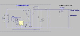
Its clear from the attached LTspice simulation, that if an OffTheShelf PSU of 48Vout (say) gets a load suddenly connected to its output, then the PSU can put out 85V transient peaks....which may well blow up the load.
Clearly this is due to the LC in its output (always present in offtheshelf PSU's). So why dont manufacturers tell us what they've put in the output so we can investigate and anticipate such overvoltages?
Why do OffThe Shelf PSU's not give the schem of their output?
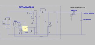
Its clear from the attached LTspice simulation, that if an OffTheShelf PSU of 48Vout (say) gets a load suddenly connected to its output, then the PSU can put out 85V transient peaks....which may well blow up the load.
Clearly this is due to the LC in its output (always present in offtheshelf PSU's). So why dont manufacturers tell us what they've put in the output so we can investigate and anticipate such overvoltages?