Continue to Site

Welcome to EDAboard.com

Welcome to our site! EDAboard.com is an international Electronics Discussion Forum focused on EDA software, circuits, schematics, books, theory, papers, asic, pld, 8051, DSP, Network, RF, Analog Design, PCB, Service Manuals... and a whole lot more! To participate you need to register. Registration is free. Click here to register now.

4 to 20mA circuit design

Status
Not open for further replies.

ss_engg

Member level 5
Joined
Mar 9, 2011
Messages
81
Helped
1
Reputation
2
Reaction score
1
Trophy points
1,288
Location
Pakistan
Activity points
1,854
Hi,

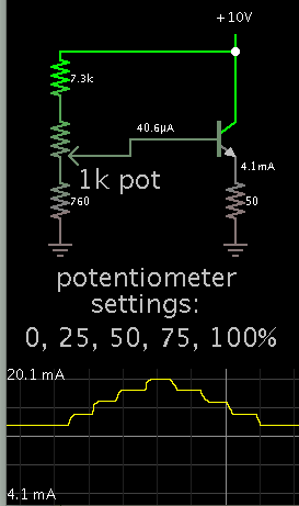
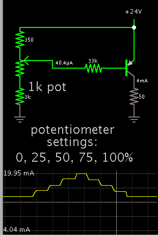
I would like to design a circuit that give me 4-20mA current using variable resistance.

There are following requirments:

0% resistance 20mA

25% resistance 16mA

50% resistance 12mA

75% resistance 8mA

100% resistance 4mA

kindly help me out to design this circuit

Thankyou
 
Last edited by a moderator:

Hi,

what do you mean with 100% resistance?

0% resistance --> 0 Ohms ?
100% resistance --> infinite Ohms ?

50% resistance --> infinite / 2 Ohms ????

Klaus
 

means at minimun value of resistance its 20mA and then gradually with 25% of that selected resistance the current should be 16mA and so on. the supply voltage should be 24 volts..

kindly help it .. schematic diagram or that circuit
 

Hi,

it´s guessing here...

I guess you decide a "max. resistance" range. This value should be 100% resistance.

For an example if you set your resistance range to 10k then:

0 Ohms --> = 20 mA,
2.5k Ohms --> 16 mA
5k Ohms --> 12 mA
..
10kOhms --> 4 mA.

************
How do you like to set your "resistance range"?

You will need completely different designs for:
* the milliohms range
* the 10k ohms range
* the GOhms range

Should it be a:
* low cost solution
* high precision solution
* most flexible solution?

Give more information, please.

Klaus
 

I would like to design a circuit of 4-20mA( which is most common circuit in industry application) with variable resistance...

selection of variable resistance is like that at Max resistance the current should be 4mA and when Mini resistance then the current should be 20mA.

How I design this circuit
 

Hi,

How I design this circuit

I don´t know if you want to select the _range_ with:
* a pot
* a switch
* connectiong a real resistor
* or else

I don´t know if it should be for milliohms, kOhms or gigaohms.

You have to tell us.

You surely have a picutre in mind about your application. Panit it and show it to us.

Klaus
 

Your request doesn't make any sense AT ALL.
We are not going to sit down and spend time designing something that has no practical application and may only answer one of the questions on an absurd test you are trying to complete.
 

I have a picture capture from internet regarding to 4-20mA current circuit..
kindly open this close picture.. and guide me ... 4-20mA_46B0E7F3-0F8C-2220-EDA0D86AFEE51E48.jpg

- - - Updated - - -

the problem is that when I apply this circuit then not get a linear relation e.g at Minimum value of resistance 20mA and at high value its 4mA but in between I'm not getting 8mA, 12mA and 16mA current steps
 

Hi,

try this one.

4_20mA.JPG

Klaus
 

The potentiometer positions can be applied to bias a transistor.

The transistor then provides your desired current levels.

7160196300_1405611017.png


The resistor values had to be custom adjusted, in order to get the desired range of output.
 

BradtheRad < kindly do tell me transistor name as well as from which point of transistor I collect the require current levels >
 

BradtheRad < kindly do tell me transistor name as well as from which point of transistor I collect the require current levels >

A general purpose NPN is suitable. It probably will need heat-sinking, if it must drop 23V at 20 mA.

The 50 ohm resistor can be replaced by your load. My simulation has the load in the emitter leg. This made it slightly easier to adjust the bias, because gain is not so sensitive to change.

On the other hand, with the load in the collector leg, gain becomes very sensitive. The bias network must contain high resistances, because the transistor is only passing a few mA.

You may find your project requires the load to be in a particular position (emitter or collector). You may find you need to use a PNP transistor instead of an NPN.
 

in my assignment it a condition to use 24vdc and variable resistor.
so in your diagram 10vdc is supply is it possible with 24vdc.??
and I measure the current levels like 4-8-12-16-20mA from emitter to ground ?? Am i right ??
 

in my assignment it a condition to use 24vdc and variable resistor.
so in your diagram 10vdc is supply is it possible with 24vdc.??

Yes. The transistor must be rated to withstand 24V.

and I measure the current levels like 4-8-12-16-20mA from emitter to ground ?? Am i right ??

That is correct.
 

in my assignment it a condition to use 24vdc and variable resistor.
so in your diagram 10vdc is supply is it possible with 24vdc.??

The resistor values have to be changed

and I measure the current levels like 4-8-12-16-20mA from emitter to ground ?? Am i right ??

No.
 

The potentiometer positions can be applied to bias a transistor.

The transistor then provides your desired current levels.

7160196300_1405611017.png


The resistor values had to be custom adjusted, in order to get the desired range of output.
That circuit does not provide a constant current output. The output current depends upon the emitter resistor whereas a constant-current source would be independent of the resistor (at least within its compliance voltage range). To make it a constant current generator you could use a PNP and connect the collector to a grounded load.
 

Hi

The above circuit has about the same function as a
500 ohms resistor and a 2000 ohms pot.
Where the 500ohms is connected to the wiper of the pot.

Klaus
 

That circuit does not provide a constant current output. The output current depends upon the emitter resistor whereas a constant-current source would be independent of the resistor (at least within its compliance voltage range). To make it a constant current generator you could use a PNP and connect the collector to a grounded load.

You are correct.

Here is a version which uses a PNP transistor, with the load in the collector leg. Supply is 24V.

Notice a bias resistor has been added in series. Gain adjustment is delicate. All resistor values must be carefully adjusted.

9079485800_1405764103.png
 

The success of both these circuits is reliant on the gain of the transistor as being 100. Very few transistors have a gain of 100.
The PNP circuit is particularly unpredictable because you have such a small voltage to play with.

The main problem with your examples is the low impedance (resistance) of the load.
Normally a 4mA to 20mA circuit produces 0v to 5v and drives into a 250R load.
 
Last edited:

You need to add a resistor in the emitter leg to provide negative feedback and stabilize the gain.
See the simulation below over the pot limits. (The horizontal axis is the pot wiper position). The circuit is relatively insensitive to the value of RLd as seen for values of 0 through 300 ohms.

To minimize the effect of the base-emitter voltage and improve stability, you can add an op amp in the feedback loop along with a voltage reference to remove the sensitivity to supply voltage.


2-20mA.gif
 
Last edited:

Status
Not open for further replies.

Similar threads

Part and Inventory Search

Welcome to EDABoard.com

Sponsor

Back
Top