Continue to Site

Welcome to EDAboard.com

Welcome to our site! EDAboard.com is an international Electronics Discussion Forum focused on EDA software, circuits, schematics, books, theory, papers, asic, pld, 8051, DSP, Network, RF, Analog Design, PCB, Service Manuals... and a whole lot more! To participate you need to register. Registration is free. Click here to register now.

4 inch common anode brightness problem

Status
Not open for further replies.

florinalex

Junior Member level 1
Joined
Jun 4, 2006
Messages
17
Helped
0
Reputation
0
Reaction score
0
Trophy points
1,281
Activity points
1,416
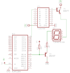
I have a setup with 6 large 7-segment common anode displays (TOS-40101BH - high brightness, 5 LEDs per segment) running multiplexed. The problem is that the display brightness is much lower than expected. I am using a ICM7228A display driver along 6 x BD677 transistors for driving the anodes and 7 x 2N2907 transistors for driving the displays' cathodes and a TD62783 for turning on the BD677 transistors. The power supply is 15V/1.5A. The whole system functions properly, but not at the expected brightness.
Can someone have a look at the attached schematic and tell me if the design is wrong? What should I do to increase the brightness of the displays?
 

Attachments

  • sch.png
    sch.png
    10.1 KB · Views: 127

That circuit seems strange. The connection of R2 to 5V will prevent T2 from ever turning off fully.

Keith

---------- Post added at 10:46 ---------- Previous post was at 10:44 ----------

I would be worthwhile looking at the voltages when the circuit is running - it should tell you what is happening.

Keith
 

Hi Keith,

The role of R2 is to keep the T2 blocked when there is no signal coming from the IC2.
Can you please give me some suggestions of improvements? I believe that the transistors are not properly biased.

Thank you,
Florin
 

I realise what R2. Is for but by going to 5V not 12V it prevents turn off. I assume it cannot go to 12V due to the other IC.

I cannot look up the chip data at the moment (on my mobile) but I would have used PNP transistors for the pull-up to 12V and NPN for the sink to ground. I don't know if that arrangement is possible with those chips as it inverts the logic. Using followers like you have done loses a lot of voltage.

If you haven't got a decent answer later I will look at the data sheets when I am at a computer.

Looking at the voltages on the circuit is the easiest way of checking what is happening.

Keith
 
Last edited:

Interestingly, the reported problem is low brightness rather than display not fully turning off.

You're right about the 5V limitation of 7228A segment outputs, to allow the segment driver to swing above 5.6V, you need npn drivers and inverters.

According to the cursory datasheet I found, the segments are made of five series connected LEDs (and as expectable, no resistor). Depending on the unspecified forward voltage, the display may turn-off fully - or at least almost - with 5.6V segment voltage. So the reason for low brightness is unclear, and as a first step, one would measure the voltages in operation, particularly the 25 ohm resistor voltage drop, that tells about the actual segment current.
 

Oops, I missed the 25 ohms resistor so my earlier comment was incorrect. The circuit is best viewed on a screen bigger than 320x240!

One thing to check is that the 12V isn't dropping i.e. that it can supply the required current.

Keith
 

Hi,
You should have base resistors for the transistors. What I feel is the problem is that the power supply voltage is dropping due to load. It does not stay fixed at 15v, but comes down to 11v or less.

Try to connect a to gnd via resistor and anode to +v and check how bright the 7-segment runs then. This will help identify the problem.

Hope this helps.
Tahmid.
 

The power supply should handle the current load - it is a switching power supply made with an LM2576 powered from a rather large transformer.
What I am worried about is that the transistors are not working at saturation. Do you think that replacing the 2N2907 transistors with an UN2003 would fix the problem? However, I am not completely convinced that the 2N2907s are the problem (as they are PNP they should go into saturation when the signal from ICM7228A goes to GND).
The problem is that I currently do not have access to the board (as it is in another country), so I would like to investigate more possible design flaws.

Thank you for your support.
 

Firstly, the way you have the circuit at the moment you don't need base resistors - all the transistors are being used as followers.

Secondly, I am sure NONE of the transistors are in saturation - they are running as followers. So you lose 0.7V across the PNP and 1.4V across the NPN (because it is a darlington). You need to change to inverting drivers with the PNP changed to NPN and vice versa. Also, even then, a darlington will not saturate so you will still lose 0.7V. If someone doesn't do so before, I will drawn a better scheme when I can.

Keith
 

You are right about the transistors running as followers. But if I remember correctly, the last time I did some measurements, the Vce of the T1 was about 4V and not 1.4V. This is why I think that the transistors are not properly biased.
The design was inspired from an application note from the ICM7228 datasheet.

Looking forward for your schematic (with some reusing of the current components, if possible).


But if I remember correctly, the last time I did some measurements, the Vce of the T1 was about 4V and not 1.4V.
I would expect 2.5 to 2.8 V, because the TD62783 has a darlington follower output, that causes an voltage drop. If you want to get rid of these various voltage drops you should use
common emitter low- and high-side drivers. But as long as the voltage marggin is sufficient, you can also adjust the current limitings resistors. Do you know the actual display forward voltage? What's the intended segment current?
 

It might have been between 2.5 .. 2.8V, it was about a year ago when I did the measurements. So the circuit is not totally bad, only that a lot of voltage is lost due to the functioning of the transistors as emitter followers. So the brightness problem could be fixed by increasing the power supply to lets say 18V and changing the current limiting resistor value so that the current through the five LEDs is 150mA.
Just to check that I understood it correctly: the circuit can remain as it is (with the two modifications mentioned before) and the voltage drops are like this: for T1: Vce = 2,5V, for display 5 x 1.8 .. 2V = 9 .. 10V and for T2: Vce = 2,6V. How can I correctly calculate the Vce in this case?

Thank you,
Florin
 

Vce for T2 should not be 2.8V - more like 0.8V. However, your figures show there is nothing left to be dropped across the 25 ohm resistor with just 15V supply. That may well be you problem. Removing the NPN darlingtons & using a normal NPN would help.

Keith
 

Status
Not open for further replies.

Part and Inventory Search

Welcome to EDABoard.com

Sponsor

Back
Top