Continue to Site

Welcome to EDAboard.com

Welcome to our site! EDAboard.com is an international Electronics Discussion Forum focused on EDA software, circuits, schematics, books, theory, papers, asic, pld, 8051, DSP, Network, RF, Analog Design, PCB, Service Manuals... and a whole lot more! To participate you need to register. Registration is free. Click here to register now.

4.7 Ohm resistor specs

Status
Not open for further replies.
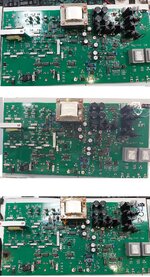
I took a top view shots for the 3 boards that are opened for repair process.

1. Check the last board, I put an arrow pointing to a wire used to connect between two points. Of course they done that to fix something.
2. The combined resistors in parallel in 2nd and 3rd, where the 1st one has one resistor in that location.

20220925_114511.jpg
 

Attachments

  • 20220925_114511.jpg
    20220925_114511.jpg
    1.4 MB · Views: 151

As far as I see, the 4R7 power resistor aren't present in the #17 schematics. So the schematic is either incomplete or belongs to a different board version, I guess the latter. This would also explain the confusion about parts with same part number but different value.

I guess that the 4R7 resistor are located in the supply of AC power amplifiers feeding the smaller transformers at the lower right board corner. They are implemented with L165 audio amplifiers in the #17 schematic and apparently different, probably with discrete transistors in the pictured board.
 
As far as I see, the 4R7 power resistor aren't present in the #17 schematics. So the schematic is either incomplete or belongs to a different board version, I guess the latter. This would also explain the confusion about parts with same part number but different value.
I'm a bit confused of this company ! there's a difference in board's model number and the number in the lab manual file name.

The board in #17 has the model 570.050.530, and the lab manual has the file name as "570.058.001 Key to Principles of Power Electronics" and when I open the file, the first page has the same board that is in the lab with the model number 570.050.530.

Even the schematics' file doesn't mention the board's model number anywhere, so you're right it's hard to tell what is going on !

I think I'm going to send them another email asking if there are other files to what exactly in the lab, because there are differences between the schematics and the actual PCB implementation.

I guess that the 4R7 resistor are located in the supply of AC power amplifiers feeding the smaller transformers at the lower right board corner. They are implemented with L165 audio amplifiers in the #17 schematic and apparently different, probably with discrete transistors in the pictured board.

Yeah, I have to study this point, when I return to the schematics, this part is for simulating 3-ph voltages for 3-ph controlled rectifiers.

But now I'm away from the office, next time I will check this part and get a photo for it.

Thanks man,
 

Status
Not open for further replies.

Part and Inventory Search

Welcome to EDABoard.com

Sponsor

Back
Top