Continue to Site

Welcome to EDAboard.com

Welcome to our site! EDAboard.com is an international Electronics Discussion Forum focused on EDA software, circuits, schematics, books, theory, papers, asic, pld, 8051, DSP, Network, RF, Analog Design, PCB, Service Manuals... and a whole lot more! To participate you need to register. Registration is free. Click here to register now.

4.7 Ohm resistor specs

Status
Not open for further replies.

eagle1109

Full Member level 6
Joined
Nov 20, 2014
Messages
390
Helped
4
Reputation
10
Reaction score
7
Trophy points
1,298
Location
Saudi Arabia
Activity points
5,928
Hi,

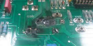
I'm doing some maintenance to training boards for power electronics. I want to know the type of this 4.7ohm resistor:

20220608_141137_resize_70.jpg


I want to purchase some from Aliexpress, but couldn't find the exact one. Is it an ordinary 4.7ohm, 2W resistor ?

When I searched about it with google lens I found results saying it's "Resistance Fusibles Métal Ohms 2 Watts".

Would something like this one be the same ?

41S1mr6NBZL._SX522_.jpg
 

It's impossible to detect an unknown resistor type from a photo, can be e.g. thin film, thick film or wirewound. Nominal power rating depends on size and maximal temperature which can be quite different. "Fusible" is a special class of resistors with fail safe overload behaviour.

If you don't have service documents for the board, you can try to derive the specification from analysis of board function.
 
I have the company official PDF manual containing all the schematic diagrams, but there's no explanation of any component specs, only values.
 

First you say it's a fusible resistor, then you say there's no information in the manual. How did you come to the conclusion it's a fusible resistor? Is it open?

I don't order parts based on a picture, I order them based on a description. (Further, your picture is of a 1K resistor).
 
I have the company official PDF manual containing all the schematic diagrams, but there's no explanation of any component specs, only values.
Hi,

So why not share the datasheet, then? - I'd like to look at it. I have 470R fusible resistors that are that colour and texture, identical to yours, which is not meant to affirm that yours are, that would be frivolous/irresponsible. Shate the datasheet.
 

If this resistor is getting blown often, do you think a better one might be 10W or more rather than 5W. Then it won't matter much what type. Carbon or metal-film.

But if you want these as fuses, string some 1/2W resistors 1+1+1+1 or 1/4W resistors 0.47 x 10
 

I used google lens. A very similar one to the I got has this name.


That's a good idea, let me next time crack it with anything and check what is inside and post it here.
That’s not what i meant. Is it open-circuit; does it measure infinite ohms?

And just because something looks the same doesn’t mean it is. Using image recognition to identify an electronic part’s specification is a terrible idea.
 
That’s not what i meant. Is it open-circuit; does it measure infinite ohms?
I actually don't really know what they do exactly, they come in series to test point outputs.

r166_r155_2.PNG


This is the board basically, it's a training board.

20220912_110032_resize_67.jpg


This is the PCB side, the picture not clear. But, I will get a better one next time.

20220608_141059_resize_50.jpg
 

I’m done.

You start off talking about a 4.7 ohm fusible resistor and then post a schematic highlighting 3.9K and 10K resistors.
 

Waiting for a better photo, but apparently the snippet of post #1 shows a different board.
 
I’m done.

You start off talking about a 4.7 ohm fusible resistor and then post a schematic highlighting 3.9K and 10K resistors.
It's a bit a complicated story.

There are 20 training boards, which went through problems; like, burnt stuff, malfunctioned parts of the board, missing +10V, -10V, ... etc.

These boards aren't identical the same, especially with these resistors, the rest is almost the same. But these resistors which are R155, R166, and other ones aren't the exact values.

And the surprising thing is that in the schematic they are 3.9K and 10K resistors but in boards I opened and they are 4.7Ohms factory soldered resistors.

A more surprising thing is that the boards with 4.7Ohms are more stable in those parts of the board, where in other boards having resistors I measured having values +30kOhms are burnt with those resistors, here are some pictures from the last repairing sessions:

The next two photos for factory soldering state, no one touched it. I have to take pictures before doing anything in the board for protecting myself against anything that could face me.

20220608_141137_resize_70.jpg


20220608_141114_resize_97.jpg


I emailed the guy who works in hera corporation about this issue of non-precise resistors values than what is used on the board and he didn't respond to me. I think he was kind enough to send me the schematics file and that's it.
 

Attachments

  • 20220901_153704_resize_43.jpg
    20220901_153704_resize_43.jpg
    174.8 KB · Views: 133

I doubt that R166 and R155 in the photo have the same circuit function as R166 and R155 in the schematic. Obviously part numbering has changed.
 
How do you burn a 30K, 1W(maybe) resistor? In order to generate 1W in a 30K you'd need 170 volts across it.
 
It's an ordinary Philips resistor, looks like the 2W variant, but hard to tell the scale, similar R's are made in 1W & 3W ... measurement and data sheet will tell all.
--- Updated ---

If there R's have died recently there is likely some other causative fault.
 

Any resistor between a fuse and big electrolytics is almost certainly part of the power supply. The ones circled in the schematic are not only different values but in places where it would be almost impossible to damage them from any internal voltage source. If the 'test points' are actually external 'patch board' sockets (the dots on the front panel) and wired together externally then it is possible some source from outside the unit damaged them but it's unlikely.

My best guess - this looks like some kind of experimenters power inverter board and it somehow allows things to be wired inappropriately and draw excess current. The resistors are probably in the PSU, maybe surge limiters and simply got overloaded by some bad configuration. Nevertheless it would be a good idea to check the devices on the heat sink, it this is a power inverter they would be prime suspects for being damaged.

Brian.
 
I doubt that R166 and R155 in the photo have the same circuit function as R166 and R155 in the schematic. Obviously part numbering has changed.

There are 20 boards in the lab. I opened several ones until now, fixed 3, still working on couple more and waiting for replacement parts.

Fixing them isn't difficult now, figuring it in the first time was hard, I know the main problem locations, mostly are those resistors, voltage regulators and its capacitors, switching transistors. The rest is ok in all the boards.

There are different stuff going on in all the boards I opened, some have different resistors and some have extra wires connected between different parts of the PCB I guess to fix some signal loss. But the circuits almost identical, I haven't found any difference in the circuits, only with resistors and extra wires.

Wait for me until I reach the office next time and take more photos.


Here are the files from the company: the lab manual and the schematics.

Also check the model number on the board, is the same one in the lab manual.

20220823_145352_resize_62.jpg

--- Updated ---

How do you burn a 30K, 1W(maybe) resistor? In order to generate 1W in a 30K you'd need 170 volts across it.

I think most the problems are because some trainees short the stuff up, but I instruct them every time to NOT power the board until I check the wiring of the experiment.

But I believe the problems come when I leave the trainee the rest of the experiment where he must take the readings with the oscilloscope in this part I don't check their wiring all the time, and some I think do stuff on their own knowledge and not knowing what they are doing exactly, but that doesn't happen all the time.

But shorting stuff is a big reason, here is a fried transistor:

20220608_141124_resize_50.jpg


This caused a smoke and the smell stayed for days in the lab.
--- Updated ---

It's an ordinary Philips resistor, looks like the 2W variant, but hard to tell the scale, similar R's are made in 1W & 3W ... measurement and data sheet will tell all.
All I have is the schematics and the lab manuals, the guy who provided me the schematics didn't respond until now as I asked him about the 4.7ohm resistors.

If there R's have died recently there is likely some other causative fault.

When trainees do the experiments correctly, I think the boards can survive, but I think any miss wiring can lead to burnt stuff.
--- Updated ---

Any resistor between a fuse and big electrolytics is almost certainly part of the power supply. The ones circled in the schematic are not only different values but in places where it would be almost impossible to damage them from any internal voltage source. If the 'test points' are actually external 'patch board' sockets (the dots on the front panel) and wired together externally then it is possible some source from outside the unit damaged them but it's unlikely.
Yep, I agree with you.

For example, if the experiment is wired correctly, but the trainee missed connecting the oscilloscope correctly, then that may caused a burnt component. And of course miss wiring the output of the experiment circuit to the load part, and maybe mix of both cases if the trainee is having a hard time comprehending the exercise principles.

My best guess - this looks like some kind of experimenters power inverter board and it somehow allows things to be wired inappropriately and draw excess current.
Yes, I attached the files related to this board, it's a power electronics experiments board contains blocks of circuits that are powered internally.

Some blocks receive control signals internally and some require external wiring, it takes anyone some time to learn and know the board properly. I don't blame the trainees if they miss wiring something, but I work as I can so no one miss connecting anything.


The resistors are probably in the PSU, maybe surge limiters and simply got overloaded by some bad configuration.
Please check the schematics file, I don't think they are surge limiters, even I'm not expert with surge limiters, but I don't think they work in the PSU area.

Nevertheless it would be a good idea to check the devices on the heat sink, it this is a power inverter they would be prime suspects for being damaged.

Those locations are for two levels of DC voltages: +15/-15V using LDRs and +10/-10V using LM7810 and LM7910.

I found in a board a LM7810 or LM7910 broken or both. One I found the capacitor to be blown:

20220825_115858_resize_49.jpg
 

Attachments

  • 570.058.001 Key to Principles of Power Electronics.pdf
    8.4 MB · Views: 153
  • Schaltplan Power Electronic Panel Version e.pdf
    204.2 KB · Views: 134
Last edited:

Lots of failed bits to fix/replace - check everything

it does appears someone has applied reverse DC power to the thing.
 
Hi,

A quick update, the guy from the company sent me the resistor datasheet.
 

Attachments

  • SERIE-PO(1).pdf
    185.3 KB · Views: 133

Status
Not open for further replies.

Part and Inventory Search

Welcome to EDABoard.com

Sponsor

Back
Top