Continue to Site

Welcome to EDAboard.com

Welcome to our site! EDAboard.com is an international Electronics Discussion Forum focused on EDA software, circuits, schematics, books, theory, papers, asic, pld, 8051, DSP, Network, RF, Analog Design, PCB, Service Manuals... and a whole lot more! To participate you need to register. Registration is free. Click here to register now.

[SOLVED] 4.479V at the upper side of Q3 (NPN)?!

Status
Not open for further replies.

edgoulart

Newbie level 4
Joined
Jan 10, 2013
Messages
5
Helped
0
Reputation
0
Reaction score
0
Trophy points
1,281
Activity points
1,323
Hi, all !

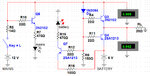
I'm a beginner in electronic. I designed a digital clock and now I'm designing an UPS to keep it running even in mains failure. My question is: Why do I have the 4.479V at the upper side of Q3 when "Key=L" is open? Shouldn't I have there just a (residual?) voltage between 0V and 2?

"Key=L" is just to simulate the lack of mains.
UPS-from-Mains
UPS-Mains.jpg

UPS-from-Battery
UPS-Battery.jpg

Thanks in advance,
Goulart
 

The residual voltage on Q3 collector when the switch is off is caused by the fact that it is the junction of R11/R6 and so you are seeing the voltage of that junction which is there to turn on Q4. Assuming that the 12V is disconnected by a switch, it isn't really a problem.

I don't know what voltage range the digital clock needs, but a couple of diodes would be a simpler method.

Keith.
 
Hi, Keith,
Thanks a lot for the nice and pronto replay!

I've been studying much at "Google school" and, according to what I've managed to learn, Q4, as a NPN, should be turned on with the absence (0V, or, with negative) voltage, not with +4.479V... This is the point I still didn't get.

I tried to put D1 before R4 to quit this "leakage", but it just dropped the voltage to 3.889V...
UPS-Battery II.jpg
... what's making me to believe Q4 is breaking down with only 6V and not with the 80V promised in its datasheet!
VCER.jpg
What mistake am I doing, or, where am I messing up?

The digital clock will needs just 250mW/6V to run. I know I could do the job with "just a couple of diodes"; but, looking at some UPS schematic I got in the net, it made me think there's much more on that! And, I'm not only interested on learning electronics, but, I'm having a great time doing that; though, sometimes, it's indeed frustrating!

Many thanks,
Goulart
 

Attachments

  • UPS-Battery II.jpg
    UPS-Battery II.jpg
    207.1 KB · Views: 104

What you are missing is the PN junction of the base-collector of Q3. When the switch is off, R11/R6 junction will be 4V or so (6V less the base emitter drop of Q4 then divided by the R6/R11). When the collector of Q3 tries to drop it forward biases the base-collector junction of Q3 - hence the voltage you are still seeing.

As I said earlier, it doesn't necessarily matter, depending on how the 12V is switched. If you are concerned about the battery bleeding back though the 12V supply when the 12V supply is connected but turned off, you could add a diode in series with the 12V supply.

Keith
 
Hi, Keith!

I believe I understood your explanation. I'll see more on the "PN junction of the base-collector" on the net 'cause I admit it's not working as I thought it should. Of course I never expected transistors to work as a perfect switch; but, right now, I'm wondering how one could call it a switch, if it spreads voltage all around! Sure I'll have to begin (once again) from the very beginning! :c)

Yes, I could place another diode before the collector of Q3; the problem is that each diode placed in the schematic it drops the voltage about 1.5V (or even more)!

If I could ask you one more question, it would be: Is there any way to use transistors as real switches? I mean, without this "spreading voltage"?

Thanks, again, for your comments,
Goulart
 

MOSFETs tend to make better switches than bipolar transistors although bipolar transistors are fine if you know what all the unwanted effects are. Even with MOSFETs you have to watch out for the body diode. One advantage of MOSFETs is the gate current is zero whereas there is a finite base current required for bipolar transistors.

Keith
 

Thanks, Keith!
I'll be looking for MOSFET's caracteristics and application.
Goulart
 

Q4, as a NPN, should be turned on with the absence (0V, or, with negative) voltage...
Q4 is PNP, not NPN.

To switch Q4 on, it's base must be about 0.7V negative relative to it's emitter. Since it's emitter is at +6V, it will switch on when it's base is at about +5.3V.
 
Q4 is PNP, not NPN. To switch Q4 on, it's base must be about 0.7V negative relative to it's emitter

Wow, thanks!
I did never understood this "negative" voltage... I always thought this should be a voltage below 0! :c)
And, thanks also for the correction on my messing up Q4/Q3.
Goulart
 

Status
Not open for further replies.

Part and Inventory Search

Welcome to EDABoard.com

Sponsor

Back
Top