KiranVSutar
Junior Member level 2
calculating 4-20 milliamp circuit
Hi All,
I had downloaded this circuit somewhere from this site.
Last 4 days I am struggling to get this 4-20 mAmp circuit to work.
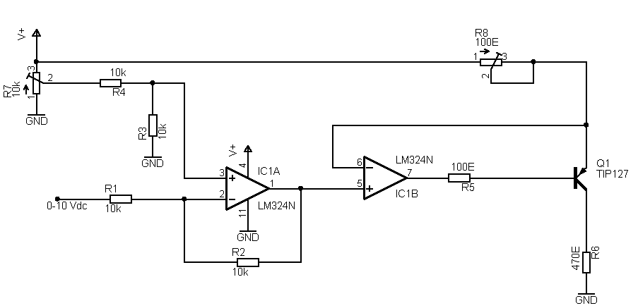
I modified the input stage of first opamp. In the original circuit the resistors R3, R4 were absent. Hence the first opamp was working like a comparator.
After putting R3,R4, this first stage is working OK.

I am getting a linear voltage 0~10 vdc at pin 1 of First Opamp.
I have blown 2 transistors but this circuit does not work.
If somebody has a different circuit, then please inform me about it, I need to get to the solution fast.
The requirements are: +12V Supply(single polarity). 0~10Vdc analog input, 4-20 mAmp or 0~20 mAmp output. Opamp to be used: LM324 or LM358.
Thanks from,
Kiran V Sutar.
Hi All,
I had downloaded this circuit somewhere from this site.
Last 4 days I am struggling to get this 4-20 mAmp circuit to work.
I modified the input stage of first opamp. In the original circuit the resistors R3, R4 were absent. Hence the first opamp was working like a comparator.
After putting R3,R4, this first stage is working OK.
I am getting a linear voltage 0~10 vdc at pin 1 of First Opamp.
I have blown 2 transistors but this circuit does not work.
If somebody has a different circuit, then please inform me about it, I need to get to the solution fast.
The requirements are: +12V Supply(single polarity). 0~10Vdc analog input, 4-20 mAmp or 0~20 mAmp output. Opamp to be used: LM324 or LM358.
Thanks from,
Kiran V Sutar.