Welcome to our site! EDAboard.com is an international Electronics Discussion Forum focused on EDA software, circuits, schematics, books, theory, papers, asic, pld, 8051, DSP, Network, RF, Analog Design, PCB, Service Manuals... and a whole lot more! To participate you need to register. Registration is free. Click here to register now.
This forum doesn't function in the way you think.
Tell us about the design scenario. Describe the problems you are facing. What part of a the code you don't understand. Show us what you done!
Members will help you in these aspects.
you are asking for something that cannot be done with digital logic, at least not as shown in the image. you can't have a signal that takes 3 distinct values. you need multiple bits our some analog circuitry.
also note that controlling delays and offsets is often hard with digital logic. you can only do multiples of the base clock.
Maybe two digital outputs driving a signal transformer / pulse transformer.
But as long as the signal is not properly specified it's just guessing.
Voltage levels, load current, complete timing, dV/dt....
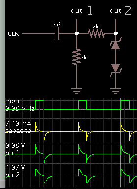
Could this be something like the analog circuitry you refer to? Your desired waveforms are not too different from the spikes which come from a series capacitor, when a DC pulse is applied.
By adding zener diodes back to back, you clamp the waveform's amplitude to whatever voltage you wish, and also make its shape more rectangular.
A simple way to generate this kind of waveforms is a differential push-pull or bridge output stage and a transformer, as used in 10BASE-T transmitter. But the question is rather vague. Do you have an input signal modulating the output, e.g. a bit stream of fixed rate? You didn't give a complete timing specification, where do we see the "25 ns" or "12.5 ns"?
This site uses cookies to help personalise content, tailor your experience and to keep you logged in if you register.
By continuing to use this site, you are consenting to our use of cookies.