Welcome to our site! EDAboard.com is an international Electronics Discussion Forum focused on EDA software, circuits, schematics, books, theory, papers, asic, pld, 8051, DSP, Network, RF, Analog Design, PCB, Service Manuals... and a whole lot more! To participate you need to register. Registration is free. Click here to register now.
A simple boost converter should do that.
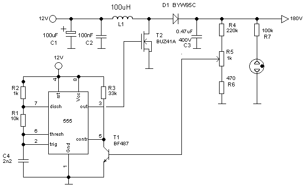
The voltages are a bit different, but the same circuit should work for you if you use a logic level mosfet. https://www.dos4ever.com/flyback/boost2.gif
Thanks Warspeed. What do you mean by "logic level mosfet"?
In case of using this scheme, do you know how can I add a current limiting protection to the output?
Most mosfets have a gate threshold voltage that is too high to work really well from only a five volt power source.
Logic level mosfets are designed especially to work directly from five volt logic signals.
You probably will not need current limiting, the output voltage will die pretty quickly if you overload the output.
However, I wonder how to obtain the optimum values for the inductor and the output capacitor for a given typical load, ie: 10mA. Any ideas?
Also, how can I know the maximum DC current allowed by the circuit. I guess I could change the load and see when the output goes down, but how would be the theoretical way to calculate this?
If we stick with one of the very common readily available 100uH toroidal chokes, and we turn on the mosfet for 30uS the current will ramp up to 1.5 amps (with 5 volts applied).
That will store 112.5 microjoules of energy.
If our switching frequency is 30 Khz (33.3uS) that will be able to ransfer 3.375 watts, assuming no losses.
So the choke charges up for 30uS and discharges into the output for 3.3uS, which it will very easily do.
The input current will average out at about half the peak, or about 0.75 amps.
A common garden variety IRF840 might just scrape by, but at 1.5 amps peak its going to very likely drop about a volt, especially with only five volts of gate drive.
Still, its probably still worth a try, as it will not be working flat out with only 5mA of actual output load.
Thanks a lot for the answers! Finally I built the power supply and it works!
The input is however 12V instead of 5V. With 5V it did not achieve 300V in the simulation....
Issues:
1. I found that the output voltage takes several minutes to stabilize. I set it for example to 300V and after a few minutes it drops to 290V. Any idea why this happens? This is not nice at all. I use 3 ceramic capacitors at the output in parallel with a 10uF tantalum capacitor.
2.Also I found that if I touch the drain of the transistor (direclty with the hand or with a metalic piece) the output drops automatically about 2V. I measured the output of the 555 timer and the with of the pulse varies a bit while I am touching the drain. Just curious to know why this happens...
This site uses cookies to help personalise content, tailor your experience and to keep you logged in if you register.
By continuing to use this site, you are consenting to our use of cookies.