Continue to Site

Welcome to EDAboard.com

Welcome to our site! EDAboard.com is an international Electronics Discussion Forum focused on EDA software, circuits, schematics, books, theory, papers, asic, pld, 8051, DSP, Network, RF, Analog Design, PCB, Service Manuals... and a whole lot more! To participate you need to register. Registration is free. Click here to register now.

3 watt Amplifire problem

Status
Not open for further replies.

Avidestroyer

Junior Member level 2
Joined
Jan 11, 2013
Messages
23
Helped
0
Reputation
0
Reaction score
0
Trophy points
1,281
Activity points
1,410
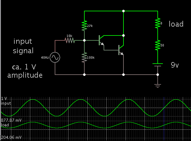
I made an 1 watt amplifire. Diagram is shown below link.
https://sci-toys.com/scitoys/scitoys/computers/solderless/small_1_watt_audio_amplifier.jpg
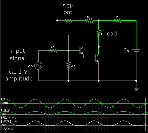
this amplifire is worked well but it is not suitable for huge bow. So I am intend to create 3 watt amplifire.
But when I add 6 transistor to this circuit instead of two, this amplifire not work, just the speaker make a sound noise. My power supply was 6 v. Why this problem occure? Plz tell me anyone.
 

A classic example of why not to trust everything you read.
This has got to be one of the most 'interesting' circuits ever.
You have to use some common-sense. When you buy an audio amplifier, does it consist of a single transistor and three resistors?
That alone should send alarm bells ringing in your head, and that's without any further knowledge of electronics.

Use the circuits shown on this site.
 

The sci-toys.com circuit is okay as a demonstration of a simple low-power audio amplifier. However it exposes the speaker to a DC component. You will risk ruining the speaker if you increase the current too much.

Just for curiosity, here is a screenshot of my simulation.

I had to reduce the upper bias resistor to 27k. This lifts the output waveform into the DC range, so that it resembles the entire range of the input signal.


Ah - I didn't spot the 50-ohm resistor (which will at least save the transistor).
However, I suspect in a real circuit, it would be very distorted because of the offset (maybe pushing
the cone to it's limit).
EDIT: Sorry, I see you've made the same point about the DC component too.
 

Oh! It's also not work. I put 6 v instead of 9 v. Is it a reason for not work?
 

A 6V supply can still power the amplifier. However to get sufficient loudness you'll need to adjust some of the component values.

Here is a screenshot of my simulation.


I reduced the 50 ohm to 15 ohm.

I placed the speaker closer to the transistor.

I added a potentiometer so that you can fine-tune the bias current to the transistor. The idea is to raise or lower the operating range, so that all of the waveform appears just above the zero V level.
 

Status
Not open for further replies.

Similar threads

Part and Inventory Search

Welcome to EDABoard.com

Sponsor

Back
Top