Johansen
Member level 4

- Joined
- Feb 10, 2008
- Messages
- 76
- Helped
- 13
- Reputation
- 26
- Reaction score
- 10
- Trophy points
- 1,288
- Activity points
- 1,844
**broken link removed**
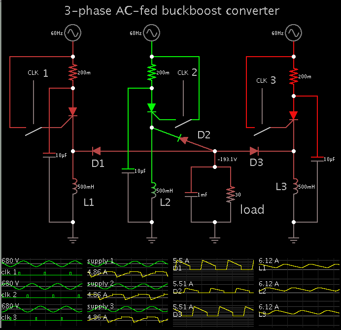
the tentative concept is 480 vac in and +/- 200 vdc out.
thoughts?
is this insane?
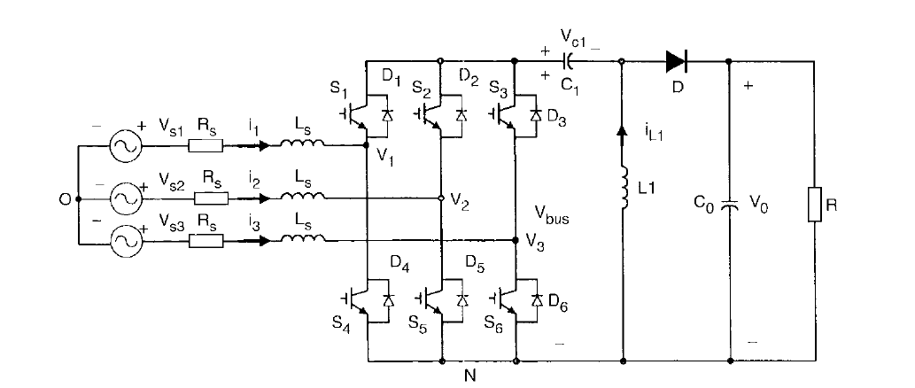
topologically the switches could be arranged in delta but then you lose the rail splitting effect.
(that and its difficult for me to imagine the switching waveforms in my mind, when the inductors and switches are connected delta)
its an improvement over other 3 phase buck/boost capable power factor converters, at the expense of twice the magnetic volume as compared to boost only PFC (I think, depending on the input voltage ratio) and you need three relatively large capacitors, as well as the WYE and or delta connected input capacitors.
other advantages are intrinsic inrush current limiting, and voltage isolation subject to the 60hz line impedance of the capacitors..
the tentative concept is 480 vac in and +/- 200 vdc out.
thoughts?
is this insane?
topologically the switches could be arranged in delta but then you lose the rail splitting effect.
(that and its difficult for me to imagine the switching waveforms in my mind, when the inductors and switches are connected delta)
its an improvement over other 3 phase buck/boost capable power factor converters, at the expense of twice the magnetic volume as compared to boost only PFC (I think, depending on the input voltage ratio) and you need three relatively large capacitors, as well as the WYE and or delta connected input capacitors.
other advantages are intrinsic inrush current limiting, and voltage isolation subject to the 60hz line impedance of the capacitors..