Continue to Site

Welcome to EDAboard.com

Welcome to our site! EDAboard.com is an international Electronics Discussion Forum focused on EDA software, circuits, schematics, books, theory, papers, asic, pld, 8051, DSP, Network, RF, Analog Design, PCB, Service Manuals... and a whole lot more! To participate you need to register. Registration is free. Click here to register now.

2nd Order low pass Butterworth filter( Shallen_Key topology) gain

Status
Not open for further replies.

varunkant2k

Full Member level 6
Joined
Nov 15, 2011
Messages
363
Helped
59
Reputation
118
Reaction score
57
Trophy points
1,308
Location
India
Activity points
3,316
Hi All,
I was trying to analyze 2nd order low pass butter worth filter. I have attached the image below.
I have few questions unresolved. I understand that , 2nd order filter response can be achieved by just connecting C1 bottom terminal to ground. Again we can provide gain independently from active device close loop gain Af = 1+R1/R2. ( image shows unity gain) ( In first order Butter worth active filter there is no such gain limit.)
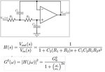
Butterworth_shallen-key filter.JPG
1. What is the advantage of connecting C1 bottom terminal to Active device output?
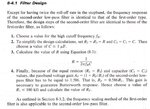
2. Why we need to give Af = G0 1+R1/R2 = 1.586 ( refer "op amp and linear integrated circuits by ramakant gaikwad") to achieve 2nd order butter worth filter response?
thanks
 

this should explain a lot:Butterworth, Chebyshev and Bessel Active Filter Design

The gain is nothing to do with the Butterworth response. It is the location of the poles and zeros that determines what the Butterworth reponse looks like

---------- Post added at 09:36 ---------- Previous post was at 09:35 ----------

... and it is the Sallen Key filter, just in case you are trying to google it
 

The gain is nothing to do with the Butterworth response.
You can't implement a RC filter with complex pole pairs without a gain element respectively a buffer (A=1). The gain becomes part of the Sallen-Key transfer characteristic and in so far has to do with the Butterworth response. For each gain value, you get specific R and C values to implement the Butterworth prototype.
 

1. What is the advantage of connecting C1 bottom terminal to Active device output?
2. Why we need to give Af = G0 1+R1/R2 = 1.586 ( refer "op amp and linear integrated circuits by ramakant gaikwad") to achieve 2nd order butter worth filter response?
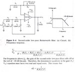
I have attached some reference image ( from the book) .
"For first case I understand that C2 forms the bootstrapping with the output and hence removes any input offset generated due to charging of C2. This also helps in adjusting the pole location."Am I Understanding correct? This is completely my statement, and can be rejected with explanation.
Butterworth_shallen-key filter_2.JPG
For second case (refer attached image) I see some relation between close loop gain of active device and second order equation in the denominator. So my question is , what are the values of poles, that will define the Gain and butter-worth correct response? here gain is the 1.568 ? any reason?
Butterworth_shallen-key filter_txt.JPG

Another question regarding fH for low pass response, What is the gain at this frequency? I get -6dB gain at this frequency. Is it correct? or I should get -3dB gain at cut off frequency for 2nd order low pass filter?
thanks
 

Usually the circuit is analyzed as feedback loop. Bootstrap is a kind of feedback as well, but I think the bootstrap concept doesn't give much insights in this case. The feedback surely hasn't to do with offsets.

The Sallen Key circuit can implement gain factors Af >= 1. A second order butterworth filter can be dimensioned for any Af value. As the quoted literature clearly tells, the gain of 1.568 is chosen to get equal resistor and capacitor values.

The butterworth prototype defines the filter Q respectively pole location. I see the mathematical criterion mentioned in the quoted literature, but not very clearly. I doubt however, that you are particularly interested in the mathematical background of filter prototypes. Personally, I ain't that much. There are edaboard members teaching electronic filters at university who may want to answer your specific questions.

The magnitude curve clearly shows a magnitude of 0.707 or -3 dB for the cut-off frequency. That's a common specification. But you can basically define a pass band with an arbitrary maximum attenuation respectively ripple of your choice.
 
Thank you FvM.
I have simulated the 2nd order low pass filter for various gain and attached the result.Butterworth_response_3.JPG
I understood that , When R1=R2 =R and C1=C2 =C, Af should be 1.586 to get -3db gain at cutoff frequency. But I wonder how they derived value 1.586, though.
feedback surely hasn't to do with offsets.
I am not having more explanation for this.I will try to find some. I understand bootstrapping improves input resistance. If low resistance at input , affects the offset.
I have few more points to add here, but too busy. I will come back again. thanks.
 

I don't exactly understand, what you have been simulating. Particularly, I don't see how yout set up a gain < 1 for a Sallen Key filter.

As said, a Sallen Key butterworth filter can be designed for different gains (Af values). The RC dimensioning has to be adjusted respectively, because you get an additional term (1-Af)R1C1s in the transfer function's denominator (besides the numerator factor Af).

The gain value of 1.586 will be obtained by adjusting Af of a filter with equal R and C to match the butterworth transfer function.

You can calculate the required gain value for a specific pole pair quality factor for the equal R and C case. It's
Af = 3 - 1/Q
Because Q is 0.71 for the second order butterworth, you get the said Af value.

The transfer functions is however only valid for an ideal OP, if you put in a real one with finite gain and non-zero output impedance, you get deviating results. The curves shown in your last post are apparently simulation results with a real OP. Generally, increasing the filter gain will reduce the loop gain and result in a higher OP related deviations.
 

Good Morning FVM, Thank you.
how yout set up a gain < 1
I did not set the gain less than 1. My simulation result shows minimum gain =1 , for voltage follower. I put marker at -2.299m dB ~1 V/V.
SO you mean Q = Chi ($) (damping factor) = 1/1.414 for critical damping and this gives Af = 1.586. I understood this. Thank you very much. So If we do not connect C2 another terminal to output of opamp, its Q will be reduced.
That means C2, adds positive feedback in the filter, that helps to improve the selectivity.
One more point here, boot-strapping does the same thing and also a positive feedback structure. ( Though schmitt trigger is also a positive f/b to add hysteresis.)
 

I see, that there is no Af < 1, I had been confused by the -xx mdB notation. So it's regular Sallen Key. According to the curves, I assume that all cases have equal R and C dimensioning as in figure 8-4. In this case, it's clear that Af = 1 shows Q < 0.7 and Af = 2 Q > 0.7.

In my literature, critical damping corresponds to Q = 0.5
 

You are correct, Critical damping is when, Chi($) = damping factor =1 and Q = 1/2. But for differential equation to give optimum response, Chi ($) is selected 0.707. and sometimes also called critical damping (under-damped response). Chi ($) = 1/2Q for second order filter.
 

Status
Not open for further replies.

Similar threads

Part and Inventory Search

Welcome to EDABoard.com

Sponsor

Back
Top