Continue to Site

Welcome to EDAboard.com

Welcome to our site! EDAboard.com is an international Electronics Discussion Forum focused on EDA software, circuits, schematics, books, theory, papers, asic, pld, 8051, DSP, Network, RF, Analog Design, PCB, Service Manuals... and a whole lot more! To participate you need to register. Registration is free. Click here to register now.

Buck Boost Driving with IR2110

Status
Not open for further replies.

geobabu

Member level 2
Joined
Jul 17, 2008
Messages
53
Helped
8
Reputation
16
Reaction score
8
Trophy points
1,288
Activity points
1,605
Hi,
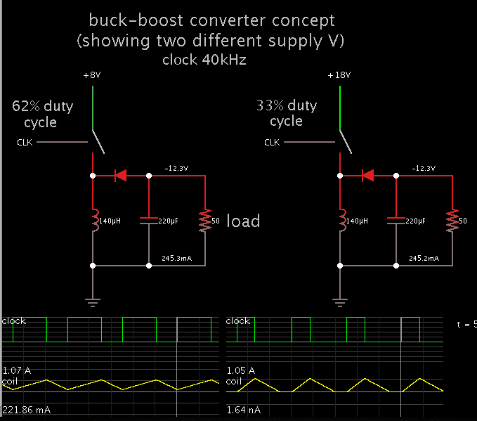
I was just trying to implement a Buck-Boost converter with a driver method as shown in the image. Since the IR2110 have individual High side and low side driving, i actually
thought this will help to avoid the using discrete components. But now I came to realize that I was wrong !
The issues I was facing ,

1) Boost operation
For boost operation (ie, switching the LOW side MOSFET Q4 ), the HIGH side MOSFET Q3, normally should be ON for provide the supply . This is not happening because the
Q3 MOSFET is not coming to ON state . I believe its because of the boost strap capacitor is not getting charged , which is usually happening through the LOW side MOSFET's ON
state if its in a HALF bridge circuit .

2) Buck Operation
The Buck circuit normally formed by switching HIGH side Q3 mosfet and keeping the LOW SIDE MOSFET Q4 always in OFF state. I believed atleast this part will work, but its
seen that, till 30% Duty Cycle, the buck part is responding as mentioned above , but after that , the PIC controller is getting heated up and all voltages are diminishing. What
would be happening here ?

The i/p voltage V_PS is just 8-18V & Vout is between 11.5 to 13-5V, and later planning to expand.

Whether all these are pointing to the fact that , IR2110 is not good for such kind of circuit. Its only work as a Half bridge mode. Could you please guide me to make this system
to a working state. What kind of driving circuits are preferred here.
BB_IR2110.png

Thanks in advance.
Regards,
Geo
 

I was just trying to implement a Buck-Boost converter with a driver method as shown in the image.

The buck-boost converter is a different topology from the buck and boost types.

The way you describe it, your circuit operates for a while as a buck converter, then for a while as a boost converter. Although this may be feasible, neither mode is buck-boost.

With a buck-boost, you vary output voltage simply by changing the duty cycle.
 

Gate drive of highside transistor Q3 won't work as intended. To keep the bootstrap circuit charged, Q3 on-time must not exceed a value of 90 or 95 %. In addition, Q3 source node must be initially pulled down to allow bootstrap start-up. Without sufficient load, D11 won't be necessarily turned on and bootstrap operation might stop.

For reliable operation, you must use a synchronous buck converter stage with low-side transistor, an auxilary bootstrap capacitor supply, or a different gate driver.
 
Thank you for your replies...
The buck-boost converter is a different topology from the buck and boost types.
When I gone through some documents , the buck boost topology is created with some different circuit. The inductor L is connected from High Side mosfet's Source to the GND. But its output is mentioned as inverting. And For the Non-Inverting type Buck-Boost converter the similar circuits are covered. As you mentioned, its actually working either as in BUCK mode (When Vin > Vout ) or in BOOST mode (When Vin < Vout) . When the Vin ~= Vout , both parts are required to control accordingly. (Found in ST's app note).

Gate drive of highside transistor Q3 won't work as intended.
Yes, the Q3 can't be held in a continuously ON state (ie 100% duty Cycle) , The boost capacitor is required to charge. usually in the Q3's OFF state. So I tried accordingly. With the smaller duty cycle, the Q3 seems to be working fine. But when the duty cycle reaches to about 30% , the PIC controller is getting heated . And voltages goes to nearly 0. What may be the cause for this heating ?

So if we are using the IR2110, only this kind of a setup (Synchronous Buck) works here ?
BB_IR2110_1.png

Can you please suggest any other high side driver , which don't have such issue ?

Regards,
Geo
 

But when the duty cycle reaches to about 30% , the PIC controller is getting heated .
This should never happen. Something seems to be wrong with your circuit.

all voltages are diminishing
Sounds weird as well.

So if we are using the IR2110, only this kind of a setup (Synchronous Buck) works here ?
Yes, this should work.

Can you please suggest any other high side driver , which don't have such issue ?
Any driver with an additional floating supply voltage, or IR2110 with an auxilary charge pump supply according to IRF or Onsemi application notes.
 

The i/p voltage V_PS is just 8-18V & Vout is between 11.5 to 13-5V, and later planning to expand.

Here is my simulation of identical buckboost converters... one has 8V supply, the other 18V.

Each has the duty cycle adjusted so that its output V is in your desired range.

Using your coil value of 140 uH, and your load of 50 ohms.


As you state, the output V is inverted polarity.
 

Thank you for the support,

This should never happen. Something seems to be wrong with your circuit.
I just tried by reducing the PWM frequency. Now its seems to the earlier 30% duty cycle margin is increased to 50% without heating. I believe its because of the Bootstrap capacitor's charging & discharging timings.

As you state, the output V is inverted polarity.
Yes the actual buck-boost circuit gives an inverted polarity , but for the inverted mode such a reference circuit is showing everywhere.

Regards,
Geo
 

Here is my simulation of identical buckboost converters... one has 8V supply, the other 18V.

Each has the duty cycle adjusted so that its output V is in your desired range.

Using your coil value of 140 uH, and your load of 50 ohms.


As you state, the output V is inverted polarity.

hello
please i need a gate driver for 2 switches buck-boost nonintervention converter by protus software
mr regards
 

Status
Not open for further replies.

Part and Inventory Search

Welcome to EDABoard.com

Sponsor

Back
Top