Continue to Site

Welcome to EDAboard.com

Welcome to our site! EDAboard.com is an international Electronics Discussion Forum focused on EDA software, circuits, schematics, books, theory, papers, asic, pld, 8051, DSP, Network, RF, Analog Design, PCB, Service Manuals... and a whole lot more! To participate you need to register. Registration is free. Click here to register now.

technique through which one can generate a Sinusoidal PWM signal using a microcontrol

Status
Not open for further replies.

styx1.618

Junior Member level 3
Joined
Oct 1, 2011
Messages
27
Helped
2
Reputation
4
Reaction score
2
Trophy points
1,283
Activity points
1,492
Hello! Can you suggest a technique through which one can generate a Sinusoidal PWM signal using a microcontroller especially PIC series ones. I want to use it as gating signal for my H-bridge- to be used as an inverter.
 

Attachments

  • SPWM.png
    SPWM.png
    85.3 KB · Views: 281

Re: Sinusoidol PWM-Gating Signal for H-Bridge using a uC

Hi, Yes it is possible to create a sine wave using a pic. you need to decide how many poles you want, meaning the resolution of the sine wave. create an array of points to be used. Then you need to design a low pass active filter to get rid of the switching noise. This should provide you with a sine wave at a frequency.
 
Re: Sinusoidol PWM-Gating Signal for H-Bridge using a uC

Take a look at these:

Generation and Implementation of Sine Wave Table
https://tahmidmc.blogspot.com/2011/01/generation-and-implementation-of-sine.html

Generation of sine wave using SPWM in PIC16F684
https://www.edaboard.com/blog/1800/

Feedback in sine wave inverter (PIC16F series based)
https://www.edaboard.com/blog/1803/

Smart Sine - Software to generate sine table
https://www.edaboard.com/blog/1798/

Demystifying The Use of Table Pointer in SPWM - Application in Sine Wave Inverter
https://tahmidmc.blogspot.com/2013/02/demystifying-use-of-table-pointer-in.html

Sine Wave Generation without ECCP - Using single CCP Module of PIC16F877A
https://tahmidmc.blogspot.com/2013/02/generation-of-sine-wave-without-eccp_16.html

Hope this helps.
Tahmid.
 
Re: Sinusoidol PWM-Gating Signal for H-Bridge using a uC

Looking at your tutorial i got the whole idea. Thanks a bunch friend for the help!
 
Last edited:

Re: Sinusoidol PWM-Gating Signal for H-Bridge using a uC

Hey i found a code for SPWM in your blog. Your description was amazing. But when i measured the carrier freq.with a counter timer in proteus, it came out to be about 7.5KHz instead of 16KHz as you have mentioned. Can you point to the problem? Thanks 1.png
 

Re: Sinusoidol PWM-Gating Signal for H-Bridge using a uC

What clock frequency did you use for PIC 16F684?
 

Re: Sinusoidol PWM-Gating Signal for H-Bridge using a uC

I'm using crystal oscillator of frequency 16MHz
 

Re: Sinusoidol PWM-Gating Signal for H-Bridge using a uC

Did you set that in the 16F684 properties? Attach the DSN file. I'd like to take a look.
 

Re: Sinusoidol PWM-Gating Signal for H-Bridge using a uC

Hello Tahmid may I have the codes in CCS C compiler which control the H-Bridge of MOSFET at high frequency in order to make a switched Mode DC-AC Converter?
For those applications of DC-AC Converters with PIC where does the 50Hz/60Hz of the output comes from? Because the H-Bridge is controlled at high frequency?
I read your blogs on :**broken link removed** and on **broken link removed** but I am not getting well the point perhaps I have to take more time.

So please can you help on the control of H-Bridge with those Sinusoidal signals,I have PIC16F1827 or PIC16F876A which I have to use for the purpose.The transformer I am suing is the high frequency transformer.


Thanks.
 
Last edited:

Re: Sinusoidol PWM-Gating Signal for H-Bridge using a uC

Hello Tahmid may I have the codes in CCS C compiler which control the H-Bridge of MOSFET at high frequency in order to make a switched Mode DC-AC Converter?
For those applications of DC-AC Converters with PIC where does the 50Hz/60Hz of the output comes from? Because the H-Bridge is controlled at high frequency?
I read your blogs on :**broken link removed** and on **broken link removed** but I am not getting well the point perhaps I have to take more time.

So please can you help on the control of H-Bridge with those Sinusoidal signals,I have PIC16F1827 or PIC16F876A which I have to use for the purpose.The transformer I am suing is the high frequency transformer.


Thanks.

Regarding frequency and any other doubts, you should get your answers here: http://tahmidmc.blogspot.com/2013/02/demystifying-use-of-table-pointer-in.html

I don't use CCS C. All the codes are in mikroC. For someone who uses CCS C, the conversion shouldn't be too difficult. Feel free to ask if there's any doubt in the mikroC codes or statements.

Hope this helps.
Tahmid.
 

Re: Sinusoidol PWM-Gating Signal for H-Bridge using a uC

Regarding frequency and any other doubts, you should get your answers here: https://tahmidmc.blogspot.com/2013/02/demystifying-use-of-table-pointer-in.html

I don't use CCS C. All the codes are in mikroC. For someone who uses CCS C, the conversion shouldn't be too difficult. Feel free to ask if there's any doubt in the mikroC codes or statements.

Hope this helps.
Tahmid.

Dear Tahmid,is it possible that I can make modifications for using PIC16F1827 for this SPWM generation for my H-bridge?With the datasheet I saw that 16F1827 has only 2 ECCP modules (are those enough?),if I use 16f876A so I have to use the syntax you use on https://http://tahmidmc.blogspot.com/2013/02/generation-of-sine-wave-without-eccp_16.html

I am using a quartz of 4Mhz,this will not affect the calculations?

Where will I change if I want to use 30Khz for example and then found 50Hz at the output?

Thanks.
 
Last edited:

Re: Sinusoidol PWM-Gating Signal for H-Bridge using a uC

Dear Tahmid,is it possible that I can make modifications for using PIC16F1827 for this SPWM generation for my H-bridge?With the datasheet I saw that 16F1827 has only 2 ECCP modules (are those enough?),if I use 16f876A so I have to use the syntax you use on https://http://tahmidmc.blogspot.com/2013/02/generation-of-sine-wave-without-eccp_16.html

You only need 1 ECCP module, not 2. So, that's enough. If you use 16F876A, you have to use the method mentioned in the link:

Sine Wave Generation without ECCP - Using single CCP Module of PIC16F877A
https://tahmidmc.blogspot.com/2013/02/generation-of-sine-wave-without-eccp_16.html

I am using a quartz of 4Mhz,this will not affect the calculations?

Where will I change if I want to use 30Khz for example and then found 50Hz at the output?

Thanks.

Please go through the link below in detail. You should get your answer.

Demystifying The Use of Table Pointer in SPWM - Application in Sine Wave Inverter
https://tahmidmc.blogspot.com/2013/02/demystifying-use-of-table-pointer-in.html

Hope this helps.
Tahmid.
 

Re: Sinusoidol PWM-Gating Signal for H-Bridge using a uC

Hello Tahmid ,I am using 16f1827 which has ECCP module,but I copied your code in MiKro c for getting an .hex file or editing referring to the PIC I am using I get the error,saying that there is no declaration of ANSEL,CMCON0,TRISC and TRISC;what can I do I normally not use MaKroC,this is my first time.

Thanks
 
Last edited:

Re: Sinusoidol PWM-Gating Signal for H-Bridge using a uC

When the compiler says that those registers are not defined that is because those registers are not present in your microcontroller. You must consult the datasheets of the two devices to find the differences between the two devices and the differing registers. Make the required changes.

Hope this helps.
Tahmid.
 

Re: Sinusoidol PWM-Gating Signal for H-Bridge using a uC

Hello Tahmid I have some couple of questions to ask you :
1.I am having trouble with not operator (in CCP1CON.P1M1 =~CCP1CON.P1M1; ) can you let me know what I can do?I am using mikroc PRO for PIC V4.60.0.0 ;the compiler is saying "Errorr.JPG"

2.See the graph I am getting in proteus when doing simulation,when getting a look the on time of the four signals and off time of them are not equal example ON Time of the last signal (green) and on time of yellow signal (what do you advice me?) for collecting those signals.

3.I have a Quartz of 4MHz and I want to generate a switching signal of 18Khz see below the code I used for getting the attached signals (I commented the line of CCP1CON1.P1M1)
Is there any other modification will I have to do for controlling my H-bridge and get 50Hz at the output?
PHP:
 unsigned char sin_table[32]={0, 25, 50, 75, 99, 121, 143, 163, 181,
198, 212, 224, 234, 242, 247, 250, 250, 247, 242, 234, 224, 212, 198,
181, 163, 143, 121, 99, 75, 50, 25,0};


unsigned int TBL_POINTER_NEW, TBL_POINTER_OLD, TBL_POINTER_SHIFT, SET_FREQ;
unsigned int TBL_temp;
unsigned char DUTY_CYCLE;

sbit MOSA at Rb0_bit;//with PIC16F876A
sbit MOSB at Rb1_bit;//with PIC16F876A
sbit MOSC at Rb2_bit;//with PIC16F876A
sbit MOSD at Rb3_bit; //with PIC16F876A

unsigned char FlagReg;
sbit Direction at FlagReg.B0;
//0 -> MOS A + D
//1 -> MOS B + C

void interrupt(){
     if (TMR2IF_bit == 1){
        TBL_POINTER_NEW = TBL_POINTER_OLD + SET_FREQ;
        if (TBL_POINTER_NEW < TBL_POINTER_OLD){
          //CCP1CON.P1M1 =~CCP1CON.P1M1; //Reverse direction of full-bridge

           if (Direction == 0){
              MOSA = 0;
              MOSD = 0;
              MOSB = 1;
              MOSC = 1;
              Direction = 1;
           }
           else{
                MOSB = 0;
                MOSC = 0;
                MOSA = 1;
                MOSD = 1;
                Direction = 0;
           }
        }
        TBL_POINTER_SHIFT = TBL_POINTER_NEW >> 11;
        DUTY_CYCLE = TBL_POINTER_SHIFT;
        CCPR1L = sin_table[DUTY_CYCLE];
        TBL_POINTER_OLD = TBL_POINTER_NEW;
        TMR2IF_bit = 0;
     }
}

void main() {
      SET_FREQ = 410;
     //SET_FREQ = 430;
     PORTB = 0;
     TRISB = 0;
     //PR2 = 249; // 16kHz
      PR2=49;   //for 20KHz
      //PR2=55; for 18KHz Generation
     CCPR1L = 0;
     CCP1CON = 12; //PWM mode
     TRISC = 0xFF;
     TMR2IF_bit = 0;
     T2CON = 0x04; //TMR2 on
     while (TMR2IF_bit == 0);
     TMR2IF_bit = 0; //Clear TMR2IF
     PORTC = 0;
     TRISC = 0;
     TMR2IE_bit = 1;
     GIE_bit = 1;
     PEIE_bit = 1;

     while (1);

}
5.on other pins (PORTB.5 and portB.6);I want to generate a square wave which has also the same frequency as the one of PWM generated;how may I proceed for that?

Thanks.


Thanks
 

Attachments

  • Oscilloscope.bmp
    919.1 KB · Views: 147
Last edited:

Re: Sinusoidol PWM-Gating Signal for H-Bridge using a uC

hello Tahmid,I used a PIC16F1827 it has an ECCP module,I want to generate an SPWM signal can you please help me to modify the codes conveniently so I can get the propoer output.
I want to control my MOSFET H-Bridge with 16KHZ,I am using a quartz of 12MHZ;the formula you are using for getting those SET_FREQ value and the Sine_Table values I am not getting it well.

Here I posted the codes I modified for getting SPMW signal on
P1A:RB3
P1B:RB5
P1C:RB6
P1D:RB7

The codes are here:
PHP:
unsigned char sin_table[32]={0,25,49,73,96,118,137,
159,177,193,208,220,231,239,245,249,250,249,245,
239,231,220,208,193,177,159,137,118,96,73,49,25};


unsigned int TBL_POINTER_NEW, TBL_POINTER_OLD, TBL_POINTER_SHIFT, SET_FREQ;
unsigned int TBL_temp;
unsigned char DUTY_CYCLE;

void interrupt(){
     if (TMR2IF_bit == 1){
        TBL_POINTER_NEW = TBL_POINTER_OLD + SET_FREQ;
        if (TBL_POINTER_NEW < TBL_POINTER_OLD){
           CCP1CON.P1M1 = ~CCP1CON.P1M1; //Reverse direction of full-bridge
        }
        TBL_POINTER_SHIFT = TBL_POINTER_NEW >> 11;
        DUTY_CYCLE = TBL_POINTER_SHIFT;
        CCPR1L = sin_table[DUTY_CYCLE];
        TBL_POINTER_OLD = TBL_POINTER_NEW;
        TMR2IF_bit = 0;
     }
}

void main() {
     SET_FREQ = 512;
     TBL_POINTER_SHIFT = 0;
     TBL_POINTER_NEW = 0;
     TBL_POINTER_OLD = 0;
     DUTY_CYCLE = 0;
      PR2=187; ///for 16Khz at 12MHZ of quartz
      TRISB=0x00;
     CCP1CON=0x4D;  //Configuration for PWM out on P1A,P1B,P1C,P1D
     TMR2IF_bit = 0;
     T2CON = 4; //TMR2 on, prescaler and postscaler 1:1
     while (TMR2IF_bit == 0);
     TMR2IF_bit = 0;
     TRISB=0;
     TMR2IE_bit = 1;
     GIE_bit = 1;
     PEIE_bit = 1;

     while(1);
}
I did whatever I can but I am not coming to the good result,I don't have output on those pins.

When I take measurements on those output pins I get a VCC output where I was supposed to get an PWM signal.

Please help on it.

Thanks.
 
Last edited:

Re: Sinusoidol PWM-Gating Signal for H-Bridge using a uC

Regarding frequency and any other doubts, you should get your answers here: https://tahmidmc.blogspot.com/2013/02/demystifying-use-of-table-pointer-in.html

I don't use CCS C. All the codes are in mikroC. For someone who uses CCS C, the conversion shouldn't be too difficult. Feel free to ask if there's any doubt in the mikroC codes or statements.

Hope this helps.
Tahmid.
Hello Tahmid here are the codes I want to use with 16f1827 but I am not succeeding about the frequencies,can you please help me for calculations?and explain I read your blog I followed the calculations overs there but I am getting nothing new.
PHP:
unsigned char sin_table[32]={0,25,49,73,96,118,137,
159,177,193,208,220,231,239,245,249,250,249,245,
239,231,220,208,193,177,159,137,118,96,73,49,25};


unsigned int TBL_POINTER_NEW, TBL_POINTER_OLD, TBL_POINTER_SHIFT, SET_FREQ;
unsigned int TBL_temp;
unsigned char DUTY_CYCLE;

void interrupt(){
     if (TMR2IF_bit == 1){
        TBL_POINTER_NEW = TBL_POINTER_OLD + SET_FREQ;
        if (TBL_POINTER_NEW < TBL_POINTER_OLD){
           CCP1CON.P1M1 = ~CCP1CON.P1M1; //Reverse direction of full-bridge
        }
        TBL_POINTER_SHIFT = TBL_POINTER_NEW >> 11;
        DUTY_CYCLE = TBL_POINTER_SHIFT;
        CCPR1L = sin_table[DUTY_CYCLE];
        TBL_POINTER_OLD = TBL_POINTER_NEW;
        TMR2IF_bit = 0;
     }
}
void main() {
     SET_FREQ = 410;
     TBL_POINTER_SHIFT = 0;
     TBL_POINTER_NEW = 0;
     TBL_POINTER_OLD = 0;
     DUTY_CYCLE = 0;
     //ANSEL = 0; //Disable ADC        commenetd myself
    // CMCON0 = 7; //Disable Comparator      commenetd myself
     //PR2 = 249;
     PR2=187; ///for 16Khz at 12MHZ of quartz
     // TRISC = 0x3F;         commenetd myself
     TRISB=0x3F;//defined myself for PWM output pins
     CCP1CON = 0x4C;
     TMR2IF_bit = 0;
     T2CON = 4; //TMR2 on, prescaler and postscaler 1:1
     while (TMR2IF_bit == 0);
     TMR2IF_bit = 0;
     TRISB=0; //defined my self for PWM out
    // TRISC = 0;               commenetd myself the PIC doesn't have portc
     TMR2IE_bit = 1;
     GIE_bit = 1;
     PEIE_bit = 1;

     while(1);
}
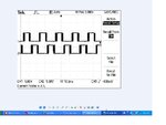
Thanks
 

Re: Sinusoidol PWM-Gating Signal for H-Bridge using a uC

I'm getting the right frequency - 50Hz.

What are you getting?
 

Re: Sinusoidol PWM-Gating Signal for H-Bridge using a uC

Tahmid, i have seen your blog "SINE WAVE GENERATION AND IMPLEMENTATION USING DSPIC33" . there i didn't find the code to configure the oscillator.
i am using another chip DSPIC33FJ32MC202 to generate SPWM, i want to configure the oscillator of this chip using internal FRC with PLL to get a Fcy of 40MHz. i am facing the problem in configuring the oscillator,i have seen the reference manual ,there a code was given in CCS. its not compiling in mikroc, can you help me to convert this code for mikroc. below is the code that i have taken from the reference manual


Example 7-2 illustrates code for using the PLL with a 7.37 MHz Internal FRC. (See also
7.11 “Clock Switching” for clock switching example code.)
Example 7-2: Code Example for Using the PLL with 7.37 MHz Internal FRC
// Select Internal FRC at POR
_FOSCSEL(FNOSC_FRC);
// Enable Clock Switching and Configure
_FOSC(FCKSM_CSECMD & OSCIOFNC_OFF);
int main()
{
// Configure PLL prescaler, PLL postscaler, PLL divisor
PLLFBD = 41; // M = 43
CLKDIVbits.PLLPOST=0; // N2 = 2
CLKDIVbits.PLLPRE=0; // N1 = 2
// Initiate Clock Switch to Internal FRC with PLL (NOSC = 0b001)
__builtin_write_OSCCONH(0x01);
__builtin_write_OSCCONL(0x01);
// Wait for Clock switch to occur
while (OSCCONbits.COSC! = 0b001);
// Wait for PLL to lock
while(OSCCONbits.LOCK! = 1) {};
}
 

Re: Sinusoidol PWM-Gating Signal for H-Bridge using a uC

Carriers.JPG
I'm getting the right frequency - 50Hz.

What are you getting?

Carriers.JPG

Hello Tahmid,the frequency of fundemental signal is ok is at 49.90Hz,but the carriers is not good it is has unspecific frequency and the form is also very bad as you see on the attachment.

Please help,but if possible let me know how you determine the SET_FREQ value and sine table (I checked on your blog where the sine table is determined from the sinus,I follow the method over there ) but I am asking my self why am I not getting the good results.

Can you help me to increase the switching frequency for my H_Bridge set it at 100KHz for example and adapt that frequency in the codes,what is the relationship between that H-bridge switching frequency and its output voltage?I applied 147VDC on the bridge but I am getting 6.6VAC as its direct output voltage.

Even in proteus the carrier signal is not good.

Thanks.

Please help.
 
Last edited:

Status
Not open for further replies.

Part and Inventory Search

Welcome to EDABoard.com

Sponsor

Back
Top