Continue to Site

Welcome to EDAboard.com

Welcome to our site! EDAboard.com is an international Electronics Discussion Forum focused on EDA software, circuits, schematics, books, theory, papers, asic, pld, 8051, DSP, Network, RF, Analog Design, PCB, Service Manuals... and a whole lot more! To participate you need to register. Registration is free. Click here to register now.

technique through which one can generate a Sinusoidal PWM signal using a microcontrol

Status
Not open for further replies.
Re: Sinusoidol PWM-Gating Signal for H-Bridge using a uC

You changed the value of PR2 since you're using a 12MHz oscillator frequency. But you did not change the sine table which was written for PR2 = 249.

You can use this sine table:

Code:
unsigned char sin_table[32]={0, 18, 36, 54, 72, 88, 104, 
119, 132, 145, 155, 165, 173, 179, 183, 186, 187, 186, 
183, 179, 173, 165, 155, 145, 132, 119, 104, 88, 72, 54, 36, 18};

You can calculate the sine table using my software Smart Sine: https://www.edaboard.com/blog/1798/

Hope this helps.
Tahmid.
 

Re: Sinusoidol PWM-Gating Signal for H-Bridge using a uC

Tahmid, i have seen your blog "SINE WAVE GENERATION AND IMPLEMENTATION USING DSPIC33" . there i didn't find the code to configure the oscillator.
i am using another chip DSPIC33FJ32MC202 to generate SPWM, i want to configure the oscillator of this chip using internal FRC with PLL to get a Fcy of 40MHz. i am facing the problem in configuring the oscillator,i have seen the reference manual ,there a code was given in CCS. its not compiling in mikroc, can you help me to convert this code for mikroc. below is the code that i have taken from the reference manual


Example 7-2 illustrates code for using the PLL with a 7.37 MHz Internal FRC. (See also
7.11 “Clock Switching” for clock switching example code.)
Example 7-2: Code Example for Using the PLL with 7.37 MHz Internal FRC
// Select Internal FRC at POR
_FOSCSEL(FNOSC_FRC);
// Enable Clock Switching and Configure
_FOSC(FCKSM_CSECMD & OSCIOFNC_OFF);
int main()
{
// Configure PLL prescaler, PLL postscaler, PLL divisor
PLLFBD = 41; // M = 43
CLKDIVbits.PLLPOST=0; // N2 = 2
CLKDIVbits.PLLPRE=0; // N1 = 2
// Initiate Clock Switch to Internal FRC with PLL (NOSC = 0b001)
__builtin_write_OSCCONH(0x01);
__builtin_write_OSCCONL(0x01);
// Wait for Clock switch to occur
while (OSCCONbits.COSC! = 0b001);
// Wait for PLL to lock
while(OSCCONbits.LOCK! = 1) {};
}

Try with something like this:

Code:
void InitClock(){
     CLKDIV = 0; // PLLPOST -> DIV BY 2
     PLLFBD = 40; // 7.37MHz/2 * 21 * 2 for VCO output
     //configured for 77.385 MHz FOSC
     
     //#define OSCCONH 0x0743
     //#define OSCCONL 0x0742
     
     asm{
         //Place the New Oscillator Selection (NOSC=0b001) in W0
         MOV #1, WREG
         //OSCCONH (high byte) Unlock Sequence
         //MOV #Lo_Addr(OSCCONH), w1
         MOV #0x0743, w1
         //MOV #OSCCONH, w1
         MOV #0x78, w2
         MOV #0x9A, w3
         MOV.B w2, [w1] // Write 0x78
         MOV.B w3, [w1] // Write 0x9A
         //Set New Oscillator Selection
         //MOV WREG, OSCCON
         MOV.B WREG, [w1]
         //Place 0x01 in W0 for setting clock switch enabled bit
         MOV #0x01, w0
         //OSCCONL (low byte) Unlock Sequence
         //MOV OSCCONL, w1
         MOV #0x0742, w1
         MOV #0x46, w2
         MOV #0x57, w3
         MOV.B w2, [w1] // Write 0x46
         MOV.B w3, [w1] // Write 0x57
         //Enable Clock Switch
         MOV.B w0, [w1]
         //Request Clock Switching by Setting OSWEN bit
     wait:
         btsc 0x0742, #0 // OSCCONL, #0
         bra wait
     }
}

I haven't tested this, but I've ported the idea over to mikroC compatible code. Let me know if this works.

Hope this helps.
Tahmid.
 
Re: Sinusoidol PWM-Gating Signal for H-Bridge using a uC

Thanks Tahmid for your response,what about SET_FREQ calculation?I used your formula but it does not match with what you calculated here of 468 with 64 values in the sine table at 12MHZ .How really may I proceed?

But I am having trouble I loaded the following codes in the 16F1827
PHP:
unsigned char sin_table[32]={0, 18, 36, 54, 72, 88, 104,
119, 132, 145, 155, 165, 173, 179, 183, 186, 187, 186,
183, 179, 173, 165, 155, 145, 132, 119, 104, 88, 72, 54, 36, 18};

unsigned int TBL_POINTER_NEW, TBL_POINTER_OLD, TBL_POINTER_SHIFT, SET_FREQ;
unsigned int TBL_temp;
unsigned char DUTY_CYCLE;

void interrupt(){
     if (TMR2IF_bit == 1){
        TBL_POINTER_NEW = TBL_POINTER_OLD + SET_FREQ;
        if (TBL_POINTER_NEW < TBL_POINTER_OLD){
           CCP1CON.P1M1 = ~CCP1CON.P1M1; //Reverse direction of full-bridge
        }
        TBL_POINTER_SHIFT = TBL_POINTER_NEW >> 11;
        DUTY_CYCLE = TBL_POINTER_SHIFT;
        CCPR1L = sin_table[DUTY_CYCLE];
        TBL_POINTER_OLD = TBL_POINTER_NEW;
        TMR2IF_bit = 0;
     }
}
void main() {
     SET_FREQ = 410;
     TBL_POINTER_SHIFT = 0;
     TBL_POINTER_NEW = 0;
     TBL_POINTER_OLD = 0;
     DUTY_CYCLE = 0;
     PR2=187; ///for 16Khz at 12MHZ of quartz
     TRISB=0x3F;// PWM output pins
     CCP1CON = 0x4C;
     TMR2IF_bit = 0;
     T2CON = 4; //TMR2 on, prescaler and postscaler 1:1
     while (TMR2IF_bit == 0);
     TMR2IF_bit = 0;
     TRISB=0; //defined my self for PWM out
     TMR2IE_bit = 1;
     GIE_bit = 1;
     PEIE_bit = 1;

     while(1);
}
;in proteus I am having the error attached on 1827DIAGRAM and with the bridge at 440VDC I am getting some 3.5VAC at the output,see the circuit at the attchment,what should be the error?

I am using IRFP460,the drive I am using are not those IR2101 but ICL7667 and at their output I am getting a good signal of 3.48V (when connecting them at 5V even when putting them at 12V nothing new).

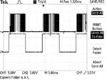
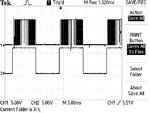
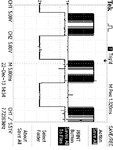
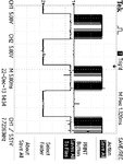
see what I am getting as controlling signal on diagonals with ICL7667 at 12V F0001TEK.JPG

Please help.

Thanks
 

Attachments

  • ProteusDIAGRAM.bmp
    2.3 MB · Views: 95
  • 1827diagram.bmp
    70.5 KB · Views: 77
  • F0000TEK.JPG
    F0000TEK.JPG
    86.6 KB · Views: 90
Last edited:

Re: Sinusoidol PWM-Gating Signal for H-Bridge using a uC

With 64 values in sine table, the number of times each value should be called is: (16,000)/(2*64*50) = 2.5
We can't do "fractional number of calls". That's why my formula doesn't "hold true".
I think 468 was a value I got by experimenting that "compensated" for the above condition to give 50Hz output.
 

Re: Sinusoidol PWM-Gating Signal for H-Bridge using a uC

can you visualise the previous posted graph (on POST #24) above and tell me what should be the correction and help me to know why I am not getting 220VAC with 440VDC?And for the values if the SET_FREQ is well calcualted,are the values in the softwares hold(give good graph??).

Thanks,please help.
 
Last edited:

Re: Sinusoidol PWM-Gating Signal for H-Bridge using a uC

Post #24 is a nightmare.

No circuit diagrams, a 2 MB screenshot of Proteus text messages that are meaningless without the referred design. Apparently you are doing something wrong but no chance to find out what you are doing at all.

The error message suggests a trivial error in the Proteus design that isn't related to inverters.
 

Re: Sinusoidol PWM-Gating Signal for H-Bridge using a uC

Hello here is the circuit diagram View attachment diagram.bmp;

May I have a good circuit using H-bridge as DC-AC Converter or be informed about the error in the diagram abobe but another problem is that even in proteus I am not getting 220VAC from 440DC,the drive I used in the snap is for simulation purposes the ones I am using on the board are ICL7667.

Please help.

Thanks

Post #24 is a nightmare.

No circuit diagrams, a 2 MB screenshot of Proteus text messages that are meaningless without the referred design. Apparently you are doing something wrong but no chance to find out what you are doing at all.

The error message suggests a trivial error in the Proteus design that isn't related to inverters.[/QUOTE]
 
Last edited:

Re: Sinusoidol PWM-Gating Signal for H-Bridge using a uC

ICL7667 is no bootstrap driver. How are you using it to drive a H-bridge?

A comment on the "simulation" circuit, a 10 uF bootstrap capacitor with 1 k load falls below the IR2101 UVLO threshold after a few ms of continuous H output. Depending on your control waveform, this may cause problems.
 

Re: Sinusoidol PWM-Gating Signal for H-Bridge using a uC

so what do you propose?On the board I don't have those capacitors but also it is not working;what should be the reason??

What is bootstrap driver??In the datasheet I found saying that the ICL7667 can be used to control the DC_DC Converters meanwhile those ones are made by MOSFET??And also for the first stage of my DC-AC converter the push pull circuit made up by two MOSFETs has been controlled using those ICL7667 and the MOSFET are working correctly.

Hello Tahmid may I know if the circuit as driver you provided on your blog https://tahmidmc.blogspot.com/2012/12/low-side-mosfet-drive-circuits-and_23.html can be used for driving H-bridge?I have a problem with my H-bridge which is giving 7VAC at output when I apply controlling signal and after powering the H-bridge with 440V I get the same voltage;I am using ICL7667 as MOSFET driver for IRFP460Z but I am thinking that those drivers are the ones which has to be replaced so because I can't find other drivers I am thinking to use transistors for driving my H-bridge.

Any suggestions please!!

Thanks.Please help
 
Last edited:

Re: Sinusoidol PWM-Gating Signal for H-Bridge using a uC

so what do you propose?On the board I don't have those capacitors but also it is not working;what should be the reason??

What is bootstrap driver??In the datasheet I found saying that the ICL7667 can be used to control the DC_DC Converters meanwhile those ones are made by MOSFET??And also for the first stage of my DC-AC converter the push pull circuit made up by two MOSFETs has been controlled using those ICL7667 and the MOSFET are working correctly.

Refer to this: https://tahmidmc.blogspot.com/2013/02/n-channel-mosfet-high-side-drive-when.html

You must first understand the difference between high and low side before you can proceed.

Hello Tahmid may I know if the circuit as driver you provided on your blog https://tahmidmc.blogspot.com/2012/12/low-side-mosfet-drive-circuits-and_23.html can be used for driving H-bridge?I have a problem with my H-bridge which is giving 7VAC at output when I apply controlling signal and after powering the H-bridge with 440V I get the same voltage;I am using ICL7667 as MOSFET driver for IRFP460Z but I am thinking that those drivers are the ones which has to be replaced so because I can't find other drivers I am thinking to use transistors for driving my H-bridge.

Any suggestions please!!

Thanks.Please help

All of those mentioned are low-side MOSFET drivers. They can only be used to drive MOSFETs in low-side configuration, not high side configuration. For H-bridge, you need two high side and two low side MOSFETs.

For H-bridge driving, you would want to use high-low side drivers. Refer to this: https://tahmidmc.blogspot.com/2013/01/using-high-low-side-driver-ir2110-with.html

Hope this helps.
Tahmid.
 

Re: Sinusoidol PWM-Gating Signal for H-Bridge using a uC

Hello Tahmid can you please help me to identify the error I have because I am applying an SPWM signal with those codes
PHP:
unsigned char sin_table[32]={0, 18, 36, 54, 72, 88, 104,
119, 132, 145, 155, 165, 173, 179, 183, 186, 187, 186,
183, 179, 173, 165, 155, 145, 132, 119, 104, 88, 72, 54, 36, 18};

unsigned int TBL_POINTER_NEW, TBL_POINTER_OLD, TBL_POINTER_SHIFT, SET_FREQ;
unsigned int TBL_temp;
unsigned char DUTY_CYCLE;

void interrupt(){
     if (TMR2IF_bit == 1){
        TBL_POINTER_NEW = TBL_POINTER_OLD + SET_FREQ;
        if (TBL_POINTER_NEW < TBL_POINTER_OLD){
           CCP1CON.P1M1 = ~CCP1CON.P1M1; //Reverse direction of full-bridge
        }
        TBL_POINTER_SHIFT = TBL_POINTER_NEW >> 11;
        DUTY_CYCLE = TBL_POINTER_SHIFT;
        CCPR1L = sin_table[DUTY_CYCLE];
        TBL_POINTER_OLD = TBL_POINTER_NEW;
        TMR2IF_bit = 0;
     }
}
void main() {
     SET_FREQ = 410;
     TBL_POINTER_SHIFT = 0;
     TBL_POINTER_NEW = 0;
     TBL_POINTER_OLD = 0;
     DUTY_CYCLE = 0;
     PR2=187; ///for 16Khz at 12MHZ of quartz
     TRISB=0x3F;// PWM output pins
     CCP1CON = 0x4C;
     TMR2IF_bit = 0;
     T2CON = 4; //TMR2 on, prescaler and postscaler 1:1
     while (TMR2IF_bit == 0);
     TMR2IF_bit = 0;
     TRISB=0; //defined my self for PWM out
     TMR2IE_bit = 1;
     GIE_bit = 1;
     PEIE_bit = 1;

     while(1);
}
on an H-bridge through the MOSFET Driver ICL7667 but I am not getting the output voltage of the H-bridge.
See the circuit in attachment and the signal I am having at the output of the Drivers.

Please help.!!

Thanks
 

Attachments

  • diagram-5.bmp
    3.1 MB · Views: 64
  • F0000TEK.JPG
    F0000TEK.JPG
    86.6 KB · Views: 88
  • F0001TEK.JPG
    F0001TEK.JPG
    86.4 KB · Views: 85
  • Like
Reactions: Zaaappp

    Zaaappp

    Points: 2
    Helpful Answer Positive Rating
Status
Not open for further replies.

Part and Inventory Search

Welcome to EDABoard.com

Sponsor

Back
Top