Continue to Site

Welcome to EDAboard.com

Welcome to our site! EDAboard.com is an international Electronics Discussion Forum focused on EDA software, circuits, schematics, books, theory, papers, asic, pld, 8051, DSP, Network, RF, Analog Design, PCB, Service Manuals... and a whole lot more! To participate you need to register. Registration is free. Click here to register now.

delay analog signal (continuous )

Status
Not open for further replies.

yanivdan98

Newbie level 6
Joined
Dec 17, 2012
Messages
11
Helped
0
Reputation
0
Reaction score
0
Trophy points
1,281
Activity points
1,368
hi

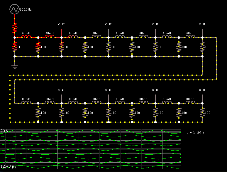
how can i implement a very simple circuit that delay analog signal (continuous signal) in X time?

i know that a diginal signal i can delay with D-FF however how can i implement a very simple circuit delay analog signal?

thanks alot
 

What time delay and what type of signal? A lumped approximation to a transmission line is one way. You can buy tapped analogue delay lines. A piece of coax cable, correctly driven and terminated, will also work.

Keith
 

hi,
thanks for answer,

for example i want to delay a sine wave signal..

what is the simplest way to implement it?

thanks
 

If you have a sine wave it is a lot easier - a simple resistor and capacitor will give a short delay. You will also lose some amplitude. There are active filters - "all pass filters" - which give time delays and preserve amplitude.

Keith
 

Capacitors and coils are able to create time delays, to a certain extent.

Example: several stages of capacitors, each connected to ground.


A square wave is applied, in order to prove it really is a time delay.

With the resistor and capacitor values shown, eight stages yields about 1/6 second. The square transitions soften and 'spread out' with each stage.

A sine wave will be delayed the same amount. However it will retain the sine wave shape.

Can any analog signal go in and come out unaffected after a similar time delay? No, it will be severely affected. Each stage attenuates highs.

The capacitors could be arranged in series, but then the effect will be difficult to interpret.
(a) With a square wave, each sharp input transition would show immediately at the output.
(b) With a sine wave they would advance the phase, which confuses our intuitive expectations.

So I did not show the results of putting the caps in series.

Coils in series will delay a signal too. However the coils need to be larger values than the capacitors. Coils tend to be bulky and costly.


If you have a sine wave it is a lot easier - a simple resistor and capacitor will give a short delay. You will also lose some amplitude. There are active filters - "all pass filters" - which give time delays and preserve amplitude.

Keith

hi

thanks you all,

what is the circuit with capacitor and cable that i need to implement?

can you show me please?

thanks
 

A capacitor/resistor solution would be simply one stage of what Brad has shown. The appropriate method depends on how much of a time delay you want for a given frequency - see "group delay.pdf".

A lumped approximation to a transmission line can give a good response - see "delay amp.pdf".

An active all pass - see "all pass.pdf"

A coax version would use a length of ordinary 50 ohm coax - see "transmission line.pdf".

A practical methods depends on the nature of the signal. Coax isn't very practical for very long delays - you need a big reel of it! Passive lumped approximations can be useful but are not so good with pulses depending on the pulse width and shape.

Keith.
 

Attachments

  • Group delay.pdf
    5.1 KB · Views: 165
  • All pass.pdf
    9.1 KB · Views: 193
  • Delay amp.pdf
    10.1 KB · Views: 166
  • Transmission line.pdf
    28 KB · Views: 122

That should delay your signal by around 220us, up to a signal of around 1kHz. How have you "calculated" it? What is your frequency?

Keith
 

however if i calculate the output signal it doesnt a delay signal?

what is the problem?
Presuming you calculated correctly, the problem might be in your expectation. The delay of a LC delay line (and even more of a single LC element) will be rather small.

The suggested analog delay methods are possibly useless if you intend large delays. In this case there won't be a "very simple circuit" available. It would be helpfully if you tell what you want to achieve.
 

Here is a simulation of the schematic from post #9.

7201972000_1356061454.png


The scope traces tell the story. At a low frequency the delay is a small fraction of a cycle. (About 1/12 cycle at 300 Hz.) This calculates to a few hundred micro-Sec.

As frequency goes up, the absolute time delay remains the same. It occupies a greater proportion of the sinewave. Hence at 1500 Hz, it is nearing 1/4 cycle.

You can apply faster frequencies, but the delay will never be greater than 1/4 cycle.
 

I know very little about delay lines, so I'll pose this as a question. Is this really delaying the signal or are we just phase shifting the current and then using the current to develop a voltage accross a resistor? Is this method commonly used to delay signals?

I have seen delay mechanisms for higher frequency, non-sinusoidal stuff where the signals are converted to another form (vibrations) and transmitted through different mediums of different lengths to acheive "true" delays
 

hi

thanks you all, i will check again the above circuit again...
also, if i have a square wave signal , how can i delay this signal? is there a simple circuit that implement it?

thanks
 

Is this really delaying the signal or are we just phase shifting the current and then using the current to develop a voltage accross a resistor? Is this method commonly used to delay signals?

The action of capacitors and coils should be distinguished from a true delay. Their delay effect comes from the fact that they take time to charge and discharge through a resistance. It only acts in the space of one waveform, and it eliminates (or attenuates) waveforms of a higher frequency, with the result that it makes the waveform more sine-like.

There are mechanical methods that produce a true delay. Example: wire springs, sound waves, light beams, lengths of wire, tape recorder.

To generate a true delay electronically, there is the analog shift register, also known as a 'bucket brigade' IC. (Radio Shack once carried the MN3002 and SAD-1024.) It's made up of thousands of capacitors on a chip. The signal is sampled, and each sample is a volt level which is applied to the first capacitor. Some internal magic is performed which transfers charge levels from one capacitor to the next, down the line until it emerges from the final capacitor, after a delay which depends on (a) the number of capacitors and (b) the clock frequency.
 

hi

thanks you all, i will check again the above circuit again...
also, if i have a square wave signal , how can i delay this signal? is there a simple circuit that implement it?

thanks

To get a useful reply you really need to give details of the signal. Frequency, shape and delay required. There are 14 posts in this thread and we still don't know that.

Keith.
 

The action of capacitors and coils should be distinguished from a true delay. Their delay effect comes from the fact that they take time to charge and discharge through a resistance. It only acts in the space of one waveform, and it eliminates (or attenuates) waveforms of a higher frequency, with the result that it makes the waveform more sine-like.

There's no principle difference between lumped LC and distributed electrical or mechanical delay lines, except for the granularity or the number of delay elements. You can also refer to an LC segment equivalent circuit of an electrical transmission line. In return, a short (< λ/10) transmission line can be represented with good accuracy by a series L and parallel C.
 

also, if i have a square wave signal , how can i delay this signal? is there a simple circuit that implement it?

thanks

A capacitor can be used to 'soften' transitions. In effect this introduces a delay.

Then an 'OR' gate (or a suitable substitute) 'cleans up' transitions and makes them sudden again.

Screenshot:

7906406500_1356461489.png


With the values shown, the pulses are delayed about 1/5 of a 200 Hz period. This works out to 1 mSec.
 

By playing with frequencies and component values, I've put together one of the most interesting simulations I've ever done.

As it turns out, enough coils can be strung together, to delay a sine wave not just 1 cycle, but 2 cycles, and more.

Screenshot:


There is a springy action that travels along the coils, which is fascinating to watch.

Here is a clickable link that will run my simulation on your computer:

https://tinyurl.com/c6v5a2y

This is a true delay. It cannot be done with one or two coils whose value is equivalent to 16 coils in series. The resistors are needed in between. However what could be done is to take a long coil, and tap it at intervals to connect the resistors, to achieve the same length of delay.

There is no limit (theoretically) as to how much time delay could be added. Every so often an amplifier would needed, since each stage attenuates the signal.

I find that a similar arrangement can be done with capacitors (connected to ground in the integrator mode, in order to delay the signal).

I also made a simulation showing that capacitors in series will advance the signal, up to 2 cycles ahead. Yes, paradoxically they will advance the signal.
 

Using inductors and capacitors as a lumped approximation to a transmission line is a well known technique for delaying signals (it was one of the example circuits I showed earlier). You can buy packaged delay lines using that technique. Like a true transmission line e.g. a piece of coax, you can have it as long as you like to create long delays. It will work with pulses down to a certain size, determined by the individual stage delay.

Keith
 

Status
Not open for further replies.

Similar threads

Part and Inventory Search

Welcome to EDABoard.com

Sponsor

Back
Top