Continue to Site

Welcome to EDAboard.com

Welcome to our site! EDAboard.com is an international Electronics Discussion Forum focused on EDA software, circuits, schematics, books, theory, papers, asic, pld, 8051, DSP, Network, RF, Analog Design, PCB, Service Manuals... and a whole lot more! To participate you need to register. Registration is free. Click here to register now.

27 MHz Amplification Query

Status
Not open for further replies.
I connected the pin 3 and pin 1 to ground and pin 2 to +5V and both the rows of the character LCD lighten up....... I think its faulty!
 

RMMK, its a simple circuit so there can't be much wrong with it. Please check these basics and let me know the results.

Voltage measurements first, with the meter negative probe on the battery negative terminal, tell me what voltages are at these points:

1. PIC pins 5 and 14. (supply pins)
2. PIC pin 4. (reset signal)
3. LCD pins 1 and 2. (supply pins)
4. LCD pin 3 with the potentiometer at each end of it's adjustment. (LCD contrast)

Then look at the LCD from a low angle and turn the potentiometer from end to end. Although you may not see any text, you should be able to see 'character box outlines' very feintly which come and go as you adjust the control.

The next suspicion would be the programming of the PIC itself.

Brian.
 

I dont think there would have been any problem in this Frequency meter circuit you have shared with me....... i will build its pcb and replace the ucontroller and lcd........ I forgot to place the 7805 IC (in my case i thought of using a 5V zener) and the circuit got powered up with 9Volts! I can smell that the lcd and ucontroller are burned! :(

- - - Updated - - -

I will try again (this time carefully) and will share results as soon as possible! I was half asleep when i was building the freq meter before........ learned the lesson harder way i guess!
 

the frequency counter is working now....... i will complete the transmitter and share the results as soon as possible!
 

Well done!

I think you will find it is an invaluable part of your development toolkit. Mine is very old now, probably dating back to about 1985 but it still works well. It can count to about 1.5GHz and about every two years I recalibrate it's oscillator although it rarely needs it.

Brian.
 

Sir I build the recommended circuit for TX2B in the below link which was somewhat like the previous design and its not working! On the recommended setup with crystal on the base-collector; my frequency counter is reading some 50Hz without the TX-2 IC but with it, it gets increased when i set the probes of my frequency counter at the base of the second transistor. I used 2N2222 transistor istead of C945 and couldnt find 203pF capacitor so ended up with the 220pF ones.
With the crystal at the base-ground; the frequency counter measure some 4MHz at the base of 2nd transistor and after that its all silent without the TX-2 IC......
I tried changing the crystal twice with a 27MHz crystal and 27.125MHz one currently in the circuit.......

http://www.talkingelectronics.com/projects/27MHz%20Transmitters/27MHzLinks-2.html#4%20CHANNEL%20TRANSMITTER

TX-2Bcct.gif

- - - Updated - - -

Chinese mark their capacitors oddly.
I think the Chinese schematic says 102P instead of 10 followed by "2" zeros which is 1,000P. They say 103P instead 10,000P.

You should find the schematic from another IC manufacturer or from a toy manufacturer.
Here is another schematic of a 27MHz toy car. It uses 20nF (20,000pF) but your schematic uses 203P (20 followed by "3" zeros) which is also 20,000pF.
Is it this way?? Is that true that the 203P implies to 20 000pF???? Isnt that really weird?
I copied the above quote from a separate thread in this forum!
 

The capacitor coding was copied from the standard resistor code, two significant digits followed by a multiplier. 102P means 10 x 10 to the power of 2 (100) = 1000pF. The 'P' varies in meaning from one manufacturer to another, sometimes it refers to the dielectric material, sometimes the temperaure coefficient.

I wouldn't recommend you measure frequency on the oscillator stage itself, that part of the circuit is sensitive to any loading you place on it, including the load of the frequency counter itself. You can safely measure it at the collector of the second transistor but there is something to be aware of: The second stage has no bias so it probably can't amplify at all. The bias comes from the IC which pulses it on and off to activate the transmission. For testing purposes, disconnect pin 8 of the IC and add a resistor (~10K) between the base of Q2 and the top of the 3V Zener diode. If you are not using the IC at all, use 33K instead and connect it to the 9V supply. That should make Q2 conduct all the time so a constant signal is produced.

Brian.
 

I was not expecting that the circuit diagram would state capacitor values in codes........
I found the code meanings in the below link:-
**broken link removed**

but would it matter much if i use 220pF capacitor in place of 20nF/ 0.02uF capacitor in the above schematic?? I feel it will not work as a decoupling capacitor in the 2nd transistor on the emitter....... am i right? I will try ur advice above!

- - - Updated - - -

by connecting one end of the 33k resistor at the base of the 2nd transistor and the other end to the +ve 9 volt will make Vb = 4.5Volts right sir?? Also I have a 5Volt/ 1Amp battery i am using since my variable power supply supplies voltage at high ripples........

- - - Updated - - -

I just checked it out and its oscillating at 13.568MHz........ Whats the reason behind this?? The crystal is placed b/w the base and collector of the first transistor as stated in the recommended circuit diagram........
 

The decoupling capaitor values are not critical so you may get away with 220pF although high values would be better.

No, although the 33K to 9V and 33K to ground may look like a potential divider, and indeed would have 4.5V at their junction if it was not for the transistor, they will actually produce a lower voltage. There is nothing wrong with that, the reason is the bottom resistor also has the B-E juntion of the transistor and the emitter resistor in parallel with it. The voltage will be lower because current is also flowing into the base but that is exactly what we want it to do at the moment so the transistor can work as an amplifier.

13.568MHz is half the frequency you want. This is a good sign, it means the oscillator is running and the frequency counter works too! It would appear you have an overtone crystal, that means it's designed to work in a frequency multiplying circuit, in this case x2. Probably the easiest way to get around this is to replace the inductor in the collector of the oscillator transistor with a tuned circuit at 27MHz. The crystal will still lock it's frequency correctly despite 'natively' runing at half that frequency.

Brian.
 

Sir basically you are saying that I need an arrangement having a parallel Inductor & capacitor at the collector of the first transistor in place of the 2.2uH inductor and the 27.125MHz overtone crystal remains at the base-collector junction...... am i right??

Also plz plz explain it to me about these types of crystals and whats the difference b/w the overtone crystal and the one (I dont know the name) that should have been in this circuit??? How can i distinguish while buying them??

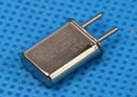
This crystal i am using is kind of an extruded rectangular shaped one...... the below one is not the one i am using but the shape is the same!
Over mine its written 27.125MHz KDG.
5560.jpg
 
Last edited:

2nd overtone sounds unlikely for a standard high frequency crystal like that in the photo because the usual crystal cut only permits odd overtones.
 

You can make the crystal work in any overtone, using a circuit like this.

5560.jpg

You must select L and C to tune in the desired frecuency:

F=1/(2*PI*SQRT(L*C))

There is not need to be exact frequency to it work, crystal will do the job. Only select the nearest coil and capacitor to get your desired frequency. If that frequency is a multiple of crystal main frequency it will oscillate.

For your example, choose:

L = 1uHY -> You can buy a inductor with this value
C=1/((48mhz*2*PI)^2 *1uHy ) = 10.99 pf -> Select a fixed 10 pF capacitor
Q1 could be a BC548 (it works up to 300mhz)

I hijacked the above from a 32 months old thread from this forum...... I think this is what you want me to do with this circuit of mine...... apart from the fact that I want the 2nd overtone and the author above required the third overtone!

- - - Updated - - -

I tried with two 30pF capacitors connected in series with each other and placed then in parallel to the 2.2uH inductor at the collector of the first transistor but i am reading now around 13.506MHz at the collector of the 2nd transistor and some 4MHz after the 47pF capacitor originating from the collector of the 2nd transistor!! how should i proceed sir??

- - - Updated - - -

with or without the 15pF capacitor (two 30pF in series) connected across the 2.2uH inductor at collector shows 13.506MHz at the collector of the 2nd transistor...... couldnt bring out the second overtone!
 
Last edited:

I agree with FvM regarding odd/even multiples of the frequency although I can't think of a mechanical reason why it shouldn't be possible. It just seems strange that you have the oscillator running at exactly half the frequency of the crystal.

The only possible explanation if the crystal is correct is that other factors are determining a lower frequency and the crystal is somehow synchronizing on every second 'kick'. Please try something for me: temporarily add a resistor of about 1K in series with the 2.2uH inductor and see what happens. If the inductor and the capacitors around it are tuning to around 13.5MHz it will reduce the 'Q' factor enough to kill most of the resonance.

Brian.
 

There should be no problem to get this to work at the desired frequency. I tried several 27 MHz CB radio crystals with this circuit, and it oscillated easily giving a good amplitude.
 

Attachments

  • 27M_xtal_osc.png
    27M_xtal_osc.png
    21.1 KB · Views: 69
  • 27M_1.png
    27M_1.png
    21.7 KB · Views: 68
Last edited:

Everybody assumes so far, that the frequency measurement is correct. Can we be sure?
 

He mentioned in post #9 that he had access to a suitable oscilloscope. He should make a measurement and verify the frequency counter reading.
 

frequency counter is working because i calibrated it with a suitable signal generator......
 

I agree with FvM regarding odd/even multiples of the frequency although I can't think of a mechanical reason why it shouldn't be possible. It just seems strange that you have the oscillator running at exactly half the frequency of the crystal.

The only possible explanation if the crystal is correct is that other factors are determining a lower frequency and the crystal is somehow synchronizing on every second 'kick'. Please try something for me: temporarily add a resistor of about 1K in series with the 2.2uH inductor and see what happens. If the inductor and the capacitors around it are tuning to around 13.5MHz it will reduce the 'Q' factor enough to kill most of the resonance.

Brian.

when i place 1Kohm resistor in series with the 2.2uH inductor on collector of the first transistor with no parallel capacitor with it......... the frequency counter shows a 4.507MHz on the collector of the 2nd transistor......

Again, with a parallel capacitor of 15pF (2- of 30pF in series) and a series resistor with 2.2uH inductor at collector of 1st transistor; gives 4.50MHz at the collector of second transistor!
 
Last edited:

I suppose it is possible the tuned circuit is picking something up at 4.5MHz and the second transistor is amplifying it. It's unlikely though.

RMMK, can you post a photograph of your construction please. Electrically, everything seems fine and I think I speak for all of us in saying we are mystified! It may be time to look at other possibile reasons why it doesn't work, the construction method being next most likely culprit.

Brian.
 

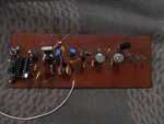
This is my construction! I haphazardly placed the 1k ohm resistor in series with the 2.2uH inductor (inductor in blue). Also the last three transistors (of PA stage) are not coupled yet since i have removed one terminal of the capacitor which couples with it......
20141006_112549.jpg

- - - Updated - - -

well when i remove the crystal... at-least i dont get any count at the collector of the 2nd transistor on my frequency counter!
 

Status
Not open for further replies.

Part and Inventory Search

Welcome to EDABoard.com

Sponsor

Back
Top