okami11408
Newbie level 4
I'm new here, I'm currently learning about basic negative feedback network and have a few question about concept of the negative feedback.
This is what I understand about negative feedback, I know that the gain of negative feedback is independent to Av because close loop gain(Af) is equal to A/(1+Aβ)
and A is very big, so Af=1/β.
----------------------------------------
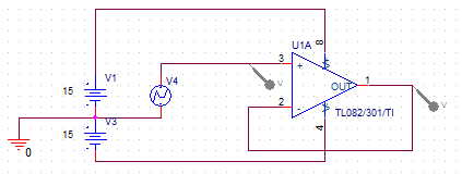
My question is according to the circuit below, why we call (Vi-Vfb) as an error signal(Vε) I mean why it's an error, and why we have to amplify that error?
And after we amplify that error we get Vout(amplified error signal) this is what confused me, we always use Vout to power something,
but it's and error signal that power something????8-O
More confusing on β circuit, I know that β is very small, why it's very small?, we amplify that error and now we want it to be small again??:shock: and that small error(Vfb) become the part of Vi??
Vi now contains 2 error signals?????
I really don't understand the whole concept of it, please help.
Sorry for my English.
Here's the image
**broken link removed**
**broken link removed**
This is what I understand about negative feedback, I know that the gain of negative feedback is independent to Av because close loop gain(Af) is equal to A/(1+Aβ)
and A is very big, so Af=1/β.
----------------------------------------
My question is according to the circuit below, why we call (Vi-Vfb) as an error signal(Vε) I mean why it's an error, and why we have to amplify that error?
And after we amplify that error we get Vout(amplified error signal) this is what confused me, we always use Vout to power something,
but it's and error signal that power something????8-O
More confusing on β circuit, I know that β is very small, why it's very small?, we amplify that error and now we want it to be small again??:shock: and that small error(Vfb) become the part of Vi??
Vi now contains 2 error signals?????
I really don't understand the whole concept of it, please help.
Sorry for my English.
Here's the image
**broken link removed**
**broken link removed**
Last edited: