Continue to Site

Welcome to EDAboard.com

Welcome to our site! EDAboard.com is an international Electronics Discussion Forum focused on EDA software, circuits, schematics, books, theory, papers, asic, pld, 8051, DSP, Network, RF, Analog Design, PCB, Service Manuals... and a whole lot more! To participate you need to register. Registration is free. Click here to register now.

Three-Axis Digital Compass IC HMC5883L

Status
Not open for further replies.

PA3040

Advanced Member level 3
Joined
Aug 1, 2011
Messages
883
Helped
43
Reputation
88
Reaction score
43
Trophy points
1,308
Activity points
6,936
Dear All
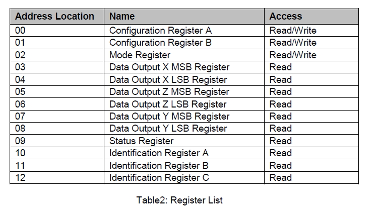
I need to write a program for above Compass and result should put to the LCD
Can I have the sample code only for compass reading and writing part
I am using 16f877a mcu
I did not see this module(HMC5883L) in the proteus and any body could know similer part number that existing Proteus please advice
Thanks in advance
 

Hi
I am also going to interface HMC5883L with 16F877A using CCS.
You need to learn I2C to interface this module. I'll update as i done it. I have placed my order.

Good Luck
Umair

- - - Updated - - -

Hi
I am also going to interface HMC5883L with 16F877A using CCS.
You need to learn I2C to interface this module. I'll update as i done it. I have placed my order.

Good Luck
Umair
 
  • Like
Reactions: PA3040

    PA3040

    Points: 2
    Helpful Answer Positive Rating
Dear Umair,
Thanks for reply
Yes I need to interface I2C to this device

Please update your experience with HMC5883L
Thanks in advance
 

The following is the basic I2C write and reads for interfacing with HMC5843, very similar to the HMC5883L. The code is written for the AVR, however the I2C write and read values should be easily adapted to Hi-Tech C Compiler, now that Alex has helped you with your I2C with the DS1307. Have you downloaded and referenced the HMC5883L datasheet, if not I strongly urge you to do so?


Code C - [expand]
1
2
3
4
5
6
7
8
9
10
11
12
13
14
15
16
17
18
19
20
21
22
23
24
25
26
27
28
29
30
31
32
33
34
35
36
37
38
39
40
41
42
43
44
45
46
47
48
49
50
51
52
53
54
55
56
57
58
59
60
61
62
63
64
65
66
67
68
69
70
71
72
73
74
75
76
77
78
79
80
81
82
83
84
85
86
87
88
89
90
91
92
93
94
95
96
97
98
99
100
101
102
103
104
105
106
107
108
109
110
111
112
113
114
115
116
117
118
119
120
121
122
123
124
125
126
127
128
129
130
131
132
133
134
135
136
137
138
139
140
141
142
143
144
145
146
147
148
149
150
151
152
153
154
155
156
157
158
159
160
161
162
163
164
165
166
167
168
169
170
171
172
173
174
175
176
177
178
179
180
181
182
183
184
185
186
187
188
189
190
191
192
193
194
195
196
197
198
199
200
201
/*
    5-18-10
    Copyright Spark Fun Electronics© 2010
    Nathan Seidle
    
    Example I2C to control the HMC5843 3-axis magnetometer
    
    Based on Aaron Weiss' code.
    
    Designed to run on an Arduino using the standard serial bootloader.
    This is not written in Arduino, this is a C example.
    
    Things to know: 
    Unlike other I2C devices, in the HMC5843 you can keep reading registers and 
    the adress pointer will continue to increment.
    
    The only register you have to write to, to get the HMC5843 to start outputting data
    is 0x02, the 'Mode' register. You have to clear bit 1 (MD1) to go into continous coversion mode.
    
    Don't forget to enable or add pullups to SDA/SCL. This firmware uses the internal
    pullups. Should work fine without them.
    
    SCL is Analog pin 5 (aka PC5)
    SDA is Analog pin 4 (aka PC4)
*/
 
#include <stdio.h>
#include <avr/io.h>
#include "i2c.h" //Needed for I2C sensors
 
#define HMC5843_W   0x3C
#define HMC5843_R   0x3D
 
//#define FALSE 0
//#define TRUE  -1
 
#define FOSC 16000000 //16MHz external osc
 
#define SERIAL_BAUD 9600
#define SERIAL_MYUBRR (((((FOSC * 10) / (16L * SERIAL_BAUD)) + 5) / 10) - 1)
 
//Function definitions
//=-=-=-=-=-=-=-=-=-=-=-=-=-=-=-=-=-=-=-=-=-=-=-=-=-=-=
void ioinit(void);
void delay_ms(uint16_t x);
void delay_us(uint16_t x);
int uart_putchar(char c, FILE *stream);
 
int16_t read_hmc5843(char reg_adr);
void init_hmc5843(void);
//=-=-=-=-=-=-=-=-=-=-=-=-=-=-=-=-=-=-=-=-=-=-=-=-=-=-=
 
//Global variables
//=-=-=-=-=-=-=-=-=-=-=-=-=-=-=-=-=-=-=-=-=-=-=-=-=-=-=
static FILE mystdout = FDEV_SETUP_STREAM(uart_putchar, NULL, _FDEV_SETUP_WRITE);
//=-=-=-=-=-=-=-=-=-=-=-=-=-=-=-=-=-=-=-=-=-=-=-=-=-=-=
 
int main (void)
{
    int16_t x, y, z;
 
    ioinit(); //Boot up defaults
 
    i2cInit(); //Get the I2C bus ready
 
    printf("HMC5843 Example\n");
 
    init_hmc5843(); //Write to 0x02 Mode register - clear MD1 bit
    
    while(1)
    {
        x = read_hmc5843(0x03);
        y = read_hmc5843(0x05);
        z = read_hmc5843(0x07);
 
        printf("x=%04d, y=%04d, z=%04d\n", x, y, z);
 
        if ((UCSR0A & _BV(RXC0))) //Check for incoming RX characters
            if(UDR0 == 'x') break;
            
        delay_ms(100); //10Hz readings by default
    }
    
    printf("You've gone too far!");
    while(1);
 
    return(0);
}
 
void ioinit(void)
{
    //1 = output, 0 = input 
    DDRB = 0b11111111;
    DDRC = 0b11111111;
    DDRD = 0b11111111;
 
    PORTC = 0b00110000; //pullups on the I2C bus
    
    //Setup USART baud rate
    UBRR0H = SERIAL_MYUBRR >> 8;
    UBRR0L = SERIAL_MYUBRR;
    UCSR0B = (1<<RXEN0)|(1<<TXEN0); //No receive interrupt
    UCSR0A ^= (1<<U2X0); //This clears the double speed UART transmission that may be set by the Arduino bootloader
 
    stdout = &mystdout; //Required for printf init
 
    //Init Timer0 for delay_us
    TCCR0B = (1<<CS01); //Set Prescaler to clk/8 : 1click = 0.5us(assume we are running at external 16MHz). CS01=1 
}
 
int16_t read_hmc5843(char reg_adr)
{       
    char lsb, msb;
 
    i2cSendStart();
    i2cWaitForComplete();
    
    i2cSendByte(HMC5843_W); // write to this I2C address, R/*W cleared
    i2cWaitForComplete();
    
    i2cSendByte(reg_adr);   //Read from a given address
    i2cWaitForComplete();
    
    i2cSendStart();
    
    i2cSendByte(HMC5843_R); // read from this I2C address, R/*W Set
    i2cWaitForComplete();
    
    i2cReceiveByte(TRUE);
    i2cWaitForComplete();
    msb = i2cGetReceivedByte(); //Read the LSB data
    i2cWaitForComplete();
 
    i2cReceiveByte(FALSE);
    i2cWaitForComplete();
    lsb = i2cGetReceivedByte(); //Read the MSB data
    i2cWaitForComplete();
    
    i2cSendStop();
    
    return( (msb<<8) | lsb);
}
 
//Setup HMC5843 for constant measurement mode
void init_hmc5843(void)
{
    i2cSendStart();
    i2cWaitForComplete();
 
    i2cSendByte(HMC5843_W); //write to the HMC5843
    i2cWaitForComplete();
 
    i2cSendByte(0x02); //Write to Mode register
    i2cWaitForComplete();
 
    i2cSendByte(0x00); //Clear bit 1, the MD1 bit
    i2cWaitForComplete();
 
    i2cSendStop();
}
 
//General short delays
void delay_ms(uint16_t x)
{
    for (; x > 0 ; x--)
    {
        delay_us(250);
        delay_us(250);
        delay_us(250);
        delay_us(250);
    }
}
 
//General short delays
void delay_us(uint16_t x)
{
    x *= 2; //Runs at 16MHz instead of normal 8MHz
 
    while(x > 256)
    {
        TIFR0 = (1<<TOV0); //Clear any interrupt flags on Timer2
        TCNT0 = 0; //256 - 125 = 131 : Preload timer 2 for x clicks. Should be 1us per click
        while( (TIFR0 & (1<<TOV0)) == 0);
        
        x -= 256;
    }
 
    TIFR0 = (1<<TOV0); //Clear any interrupt flags on Timer2
    TCNT0 = 256 - x; //256 - 125 = 131 : Preload timer 2 for x clicks. Should be 1us per click
    while( (TIFR0 & (1<<TOV0)) == 0);
}
 
int uart_putchar(char c, FILE *stream)
{
    if (c == '\n') uart_putchar('\r', stream);
  
    loop_until_bit_is_set(UCSR0A, UDRE0);
    UDR0 = c;
 
    return 0;
}


The following is a tutorial pertaining to the HMC5883L and the Arduino, however here again you should be able to adapt/port the code to the PIC using the Hi-Tech C Compiler and your I2C routines:

Triple Axis Magnetometer - HMC5883L Breakout Landing Page


I have also provided the entire project as an attachment.

BigDog
 

Attachments

  • hmc5843.zip
    14.4 KB · Views: 190
  • Like
Reactions: PA3040

    PA3040

    Points: 2
    Helpful Answer Positive Rating
Apparently the device is initialized into Continuous-Measurement Mode.

Reference: 3-Axis Digital Compass IC HMC5883L Datasheet, Section: OPERATIONAL EXAMPLES

OPERATIONAL EXAMPLES

The HMC5883L has a fairly quick stabilization time from no voltage to stable and ready for data
retrieval. The nominal 56 milli-seconds with the factory default single measurement mode means that
the six bytes of magnetic data registers (DXRA, DXRB, DZRA, DZRB, DYRA, and DYRB) are filled with a
valid first measurement.

To change the measurement mode to continuous measurement mode, after the power-up time send the
three bytes:

0x3C 0x02 0x00

This writes the 00 into the second register or mode register to switch from single to continuous
measurement mode setting. With the data rate at the factory default of 15Hz updates, a 67
milli-second typical delay should be allowed by the I2C master before querying the HMC5883L data
registers for new measurements. To clock out the new data, send:

0x3D, and clock out DXRA, DXRB, DZRA, DZRB, DYRA, and DYRB located in registers 3 through 8. The
HMC5883L will automatically re-point back to register 3 for the next 0x3D query. All six data
registers must be read properly before new
data can be placed in any of these data registers.

Below is an example of a (power-on) initialization process for “continuous-measurement mode”:

1. Write CRA (00) – send 0x3C 0x00 0x70 (8-average, 15 Hz default, normal measurement)
2. Write CRB (01) – send 0x3C 0x01 0xA0 (Gain=5, or any other desired gain)
3. Write Mode (02) – send 0x3C 0x02 0x00 (Continuous-measurement mode)
4. Wait 6 ms or monitor status register or DRDY hardware interrupt pin
5. Loop

Send 0x3D 0x06 (Read all 6 bytes. If gain is changed then this data set is using previous gain)

Convert three 16-bit 2’s compliment hex values to decimal values and assign to X, Z, Y,
respectively. Send 0x3C 0x03 (point to first data register 03)

Wait about 67 ms (if 15 Hz rate) or monitor status register or DRDY hardware interrupt pin

End_loop


The following code retrieves the Most Significant Byte (MSB) and the Least Significant Bytes (LSB) values from each consecutive register and recombines them into a 2 byte integral type, by first shifting the MSB by 8-bit and then ORing the result with the LSB.

I would strongly recommend first casting the MSB value as a 2-byte unsigned integral type, "unsigned int" in the case of Hi-Tech C Compiler, before shifting. Otherwise you could potentially end up with a zero result, by shifting the entire contents out of the single byte of storage.


Code:
    x = Wire.receive()<<8; //X msb
    x |= Wire.receive(); //X lsb
    z = Wire.receive()<<8; //Z msb
    z |= Wire.receive(); //Z lsb
    y = Wire.receive()<<8; //Y msb
    y |= Wire.receive(); //Y lsb

Does the above explanation clarify the code in question?

BigDog
 
  • Like
Reactions: PA3040

    PA3040

    Points: 2
    Helpful Answer Positive Rating
Dear Bigdog
Now my HMC5883l reader is working fine,
and I converted raw data to degree using following formula
Code:
float headingDegrees = atan2((double)raw_y,(double)raw_x)* 180 / 3.14159265 + 180;
Finally I need to send result to LCD,but LCD support ASCII format, just I need to know how convert the value of headingDegrees to ASCII
Please help
 
Last edited:

what are the expected values for headingDegrees ?
 
  • Like
Reactions: PA3040

    PA3040

    Points: 2
    Helpful Answer Positive Rating
Dear Alex
Thanks for reply to my 3Three axis project
it should be varying degree 0 to degree 360
But I do not know the exact format of headingDegrees
But I can explain where headingDegrees coming from
Please advice
 

Finally I need to send result to LCD,but LCD support ASCII format, just I need to know convert value of headingDegrees to ASCII

The simplest method is to utilize the sprintf() routine to convert a float type to ASCII string:


Reference:HI-TECH C® for PIC10/12/16 User’s Guide, Section: SPRINTF, VSPRINTF, Page: 220
SPRINTF, VSPRINTF

Synopsis

#include <stdio.h>
int sprintf (char * buf, const char * fmt, ...)
#include <stdio.h>
#include <stdarg.h>

int vsprintf (char * buf, const char * fmt, va_list ap)

Description

The sprintf() function operates in a similar fashion to printf(), except that instead of placing
the converted output on the stdout stream, the characters are placed in the buffer at buf. The
resultant string will be null terminated, and the number of characters in the buffer will be
returned.

The vsprintf() function is similar to sprintf() but takes a variable argument list rather than a
list of arguments. See the description of va_start() for more informa- tion on variable argument
lists.

See Also

printf(), sscanf()

Return Value
Both these routines return the number of characters placed into the buffer.


sprintf example

A Little C Primer/The C sprintf Function

Of course you could also write your own routine to convert float types to ASCII strings, if code storage needs to be conserved.

BigDog
 
  • Like
Reactions: PA3040

    PA3040

    Points: 2
    Helpful Answer Positive Rating
I'm not sure of what exactly you'll get and how many digits you need to show.

One option is to use sprintf function to convert the float to a string and show it in the display.
The alternative is to multiply the float with a power of 10 to convert it to a integer and then convert this to a string with a custom function like https://www.edaboard.com/blog/1072/
 
  • Like
Reactions: PA3040

    PA3040

    Points: 2
    Helpful Answer Positive Rating
By the way, do you intend on compensating for Magnetic Declination?

Depending on your locale, the error introduced by the phenomenon can be quite significant.


BigDog
 

Dear Alex
Still I can not use printf() function

This is my degree converter
float headingDegrees = atan2((double)raw_y,(double)raw_x)* 180 / 3.14159265 + 180;
Now I need to convert "headingDegrees" which is float to ascii

This is my LCD function ()

lcddata();

Please explain printf() function using above variables

Please help
 

Use of the printf() routine requires the writing of a small driver module. If you have existing LCD routines which can handle a string, then the simplest method would be to create a string using sprintf() routine.

Example:
Code:
#include <stdio.h>
 
   void main()
   {
      char buf[17];
      float headingDegrees = 181.123f;
      sprintf( buf, "Degrees: %7.3f", headingDegrees );
      putslcd( buf );
   }

Substitute your string to LCD routine for putslcd().

BigDog


@ Alex - Sorry!
 
actually we said sprintf that stores the result in a string

Code:
char lcd_buffer[16];

sprintf(lcd_buffer,"%f",headingDegrees);

There are additional formating parameters you can use for fixed digits or you can add text after the number etc

- - - Updated - - -

You got me again....

- - - Updated - - -

By the way, in order to use sprintf with floats in AVR there are some additional flags that have to be added , I'm not sure if you have to enable a setting in your compiler too.
 
  • Like
Reactions: PA3040

    PA3040

    Points: 2
    Helpful Answer Positive Rating
Dear Bigdog,
Thank for reply
This is my LCD routine but nothing display please advice

Code:
void display (){
lcdcmd(0x80);

float headingDegrees = 181.123f;
sprintf( buf, "Degrees: %7.3f", headingDegrees );
      	lcddata( buf );

}
buf array I define top of the program
 

Does your lcddata() routine accept a pointer of type char?

In other words can the routine successfully output the following:

Code:
lcddata("Test LCD Output");

Can you post your code for the LCD routines, including lcddata()?

Also what size is your display, 16x2, 20x2, etc?

BigDog
 
  • Like
Reactions: PA3040

    PA3040

    Points: 2
    Helpful Answer Positive Rating
Dear Bigdog
Really thanks for prompt reply

My LCD is 16x2
It Does not display lcddata {"Test LCD output"}; This format not supports

It is support lcddata {'A','B','C......'Z'};

Code:
void lcd_init(){
TRISD	= 0;
TRISB	= 0;
LCD_EN =0;
__delay_ms(175);
lcdcmd(0x38);
__delay_ms(175);
lcdcmd(0x0e);
__delay_ms(15);
lcdcmd(0x01);
__delay_ms(10);
lcdcmd(0x06);
__delay_ms(10);
lcdcmd(0x80);
__delay_ms(10);
lcdcmd(0x0c);
__delay_ms(10);
				}

Code:
void lcddata(unsigned char value)
	{
LCD_DATA = value;
LCD_RS = 1; 
LCD_RW = 0;
LCD_EN = 1;
__delay_ms (1);
LCD_EN = 0;

	}

Code:
void lcdcmd(unsigned char value)
	{
LCD_DATA = value;
LCD_RS = 0;
LCD_RW = 0;
LCD_EN = 1;
__delay_ms (1);
LCD_EN = 0;
	}


Please advice
Thanks in advance

- - - Updated - - -

Dear Bigdog
Please give me a bit time, I think it is my mistake
sorry for I am wasting your valuable time

- - - Updated - - -

Dear Bigdog
It is working
Thanks again and again for kind help
 
Last edited:

You'll need to write a LCD routine which can handle strings.

Try the following routine based on your lcddata().

Example:
Code:
void
lcd_puts(const char * s)
{
	while(*s)
		lcddata(*s++);
}

void lcddata(unsigned char value)
{
	LCD_DATA = value;
	LCD_RS = 1; 
	LCD_RW = 0;
	LCD_EN = 1;
	__delay_ms (1);
	LCD_EN = 0;

}

Modified Code:
Code:
void display ()
{
	lcdcmd(0x80);

	float headingDegrees = 181.123f;
	sprintf( buf, "Degrees: %7.3f", headingDegrees );
      	lcd_puts( buf );

}


The following is a set of LCD routines for the 16F using the 4-bit interface, however they can be adapted to an 8-bit interface like your current implementation. I have also attached a sample app in a Zip file with the following LCD routines.

lcd.h
Code:
/*
 *	LCD interface header file
 *	See lcd.c for more info
 */

/* write a byte to the LCD in 4 bit mode */

extern void lcd_write(unsigned char);

/* Clear and home the LCD */

extern void lcd_clear(void);

/* write a string of characters to the LCD */

extern void lcd_puts(const char * s);

/* Go to the specified position */

extern void lcd_goto(unsigned char pos);
	
/* intialize the LCD - call before anything else */

extern void lcd_init(void);

extern void lcd_putch(char);

/*	Set the cursor position */

#define	lcd_cursor(x)	lcd_write(((x)&0x7F)|0x80)

lcd.c
Code:
/*
 *	LCD interface example
 *	Uses routines from delay.c
 *	This code will interface to a standard LCD controller
 *	like the Hitachi HD44780. It uses it in 4 bit mode, with
 *	the hardware connected as follows (the standard 14 pin 
 *	LCD connector is used):
 *	
 *	PORTD bits 0-3 are connected to the LCD data bits 4-7 (high nibble)
 *	PORTA bit 3 is connected to the LCD RS input (register select)
 *	PORTA bit 1 is connected to the LCD EN bit (enable)
 *	
 *	To use these routines, set up the port I/O (TRISA, TRISD) then
 *	call lcd_init(), then other routines as required.
 *	
 */

#ifndef _XTAL_FREQ
 // Unless specified elsewhere, 4MHz system frequency is assumed
 #define _XTAL_FREQ 4000000
#endif


#include	<htc.h>
#include	"lcd.h"

#define LCD_RS	RA3
#define LCD_RW	RA2
#define LCD_EN	RA1

#define LCD_DATA	PORTD

#define	LCD_STROBE()	((LCD_EN = 1),(LCD_EN=0))

/* write a byte to the LCD in 4 bit mode */

void
lcd_write(unsigned char c)
{
	__delay_us(40);
	LCD_DATA = ( ( c >> 4 ) & 0x0F );
	LCD_STROBE();
	LCD_DATA = ( c & 0x0F );
	LCD_STROBE();
}

/*
 * 	Clear and home the LCD
 */

void
lcd_clear(void)
{
	LCD_RS = 0;
	lcd_write(0x1);
	__delay_ms(2);
}

/* write a string of chars to the LCD */

void
lcd_puts(const char * s)
{
	LCD_RS = 1;	// write characters
	while(*s)
		lcd_write(*s++);
}

/* write one character to the LCD */

void
lcd_putch(char c)
{
	LCD_RS = 1;	// write characters
	lcd_write( c );
}


/*
 * Go to the specified position
 */

void
lcd_goto(unsigned char pos)
{
	LCD_RS = 0;
	lcd_write(0x80+pos);
}
	
/* initialise the LCD - put into 4 bit mode */
void
lcd_init()
{
	char init_value;

	ADCON1 = 0x06;	// Disable analog pins on PORTA

	init_value = 0x3;
	TRISA=0;
	TRISD=0;
	LCD_RS = 0;
	LCD_EN = 0;
	LCD_RW = 0;
	
	__delay_ms(15);	// wait 15mSec after power applied,
	LCD_DATA	 = init_value;
	LCD_STROBE();
	__delay_ms(5);
	LCD_STROBE();
	__delay_us(200);
	LCD_STROBE();
	__delay_us(200);
	LCD_DATA = 2;	// Four bit mode
	LCD_STROBE();

	lcd_write(0x28); // Set interface length
	lcd_write(0xF); // Display On, Cursor On, Cursor Blink
	lcd_clear();	// Clear screen
	lcd_write(0x6); // Set entry Mode
}


BigDog
 

Attachments

  • LCDemo.zip
    1.8 KB · Views: 104
  • Like
Reactions: PA3040

    PA3040

    Points: 2
    Helpful Answer Positive Rating
I am not good enough like Bigdog! and also not good at pointers,so I use this method to send int or float values to LCD. (16*2)

It is Simple math.:p
lets say i have 123.456degree and I want to print 123.45
0---int temp;
1---temp=123.456*100=12345 //I suppose 2 decimal places so multiplied 100
2---temp=12345;
3---ch1=temp/10000+48; //ch1=1 ; 48 is added to convert int to ASCII
4---temp=temp%10000; //temp=2345
5---ch2=temp/1000+48; //ch2=2
6---temp=temp%1000; //temp=345
7---ch3=temp/100+48; //ch1=3
8---temp=temp%100; //temp=45
9---ch4=temp/10+48; //ch1=4
10---ch5=temp%10+48; //temp=5

Now you can use LCD character write function,

void write(char x)
{
PORTD=x; //data send to PORTD
rs=1; //is data not command.
rw=0; //is write not read.
e=0; //pull low enable signal.
delay_ms(5); //for a while.
e=1; //pull high to build the rising edge.
}

HOW to use in main function.
write(ch1)

Hope it works for you
Umair
 

Dear All,
My Three-Axis Digital Compass IC HMC5883L sensor reading is working up to 90%
Before I continue further I need to understand some informations which related to theory

Three Axis compass has six register's ( two for X , two for Y , two for z )
That mean 16bit or two 8byte register's

when we need to read x Axis we have to read two register's

Like This

Code:
msb 	=I2CRead();
	I2CAck();
	lsb =I2CRead();
	I2CAck();
	raw_z=( (msb<<8) | lsb);

First we need read msb and then read lsb and msb shift 8 times and OR with lsb

I need to verify
why shift 8 times and what are the data this two registers contain (Data Output X Registers A and B)
why we can not use single register instead of two registers
Please advice

Thanks in advance
 

Status
Not open for further replies.

Part and Inventory Search

Welcome to EDABoard.com

Sponsor

Back
Top