Continue to Site

Welcome to EDAboard.com

Welcome to our site! EDAboard.com is an international Electronics Discussion Forum focused on EDA software, circuits, schematics, books, theory, papers, asic, pld, 8051, DSP, Network, RF, Analog Design, PCB, Service Manuals... and a whole lot more! To participate you need to register. Registration is free. Click here to register now.

Internal pull up vs internal pulldown

Status
Not open for further replies.

shaiko

Advanced Member level 5
Joined
Aug 20, 2011
Messages
2,644
Helped
303
Reputation
608
Reaction score
297
Trophy points
1,363
Activity points
18,302
My question is about open collector IC outputs.

Is it true that pull up resistors are used with NPN transistors while pull down resistors are used with PNP ?
 

**broken link removed**
 

These don't answer my question
 

I know that pull up resistors are used on the open drain output of an NPN transistor.
Using a pull down with an NPN in the same way won't work - so I was wondering if a PNP must be used for pull down resistors
 

Are you asking about the resistor connected to the collector?
 

When you have a NPN operating as a low side switch then the emitter is connected to the ground and you drive the base with a positive voltage to turn it on.
When the transistor is on then it sinks current, basically it provides ground to whatever is connected to the collector.
When the transistor is off then the collector is in a high resistance state which is like floating.
If you want to force the collector to a known high state when off then you can connect what you call a pullup resistor, it is basically like a load, when the transistor is off no current flows through the resistor so there is no voltage drop and the collector becomes high.
When the transistor turns on then the current that flows through the pullup resistor creates a voltage drop so the collector goes to a low state.

for a PNP everything I said is reversed.
The emitter is connected to the positive supply and you turn the transistor on with a voltage lower that the emitter supply.
The transistor sources current when turned on ( it provided supply to the collector) or leaves it floating when it is off.
If you want to force a state when the transistor is off then it only makes sense to use a pull-down resistor connected to ground.

Alex
 
So,
If I use programmable internal pullups or pulldown in a "smart IC" (like an FPGA or MCU) the tool automatically knows to select the correct transistor to use on the silicon fabric according to the pull type I requested?

NPN for pull up
PNP for pulldown

Is this correct ?
 

My question is about open collector IC outputs.

Is it true that pull up resistors are used with NPN transistors while pull down resistors are used with PNP ?
Yes, that's right.
 
  • Like
Reactions: shaiko

    shaiko

    Points: 2
    Helpful Answer Positive Rating
Note that a pull up.down resistor is not always needed.
For example with a ULN2003 you can connect a relay or a motor directly between the collector and supply, when the transistor is on then current will flow through the load and it will rotate or switch on .
When the transistor turns off then there is no current flow so a motor or a relay will turns off.

---------- Post added at 17:41 ---------- Previous post was at 17:32 ----------

So,
If I use programmable internal pullups or pulldown in a "smart IC" (like an FPGA or MCU) the tool automatically knows to select the correct transistor to use on the silicon fabric according to the pull type I requested?

NPN for pull up
PNP for pulldown

Is this correct ?

I have worked with some devices that had a user programmable ground that could be enabled but that was only to force a known state in unused inputs to reduce consumption.

Are your outputs open collector?
Are you sure that your device has output pull up/down?

In any case I don't think there is any smart selection involved, if there are two options then the user must select the proper one.
I may be wrong of course.

Alex

---------- Post added at 17:44 ---------- Previous post was at 17:41 ----------

This is a quote from Spartan3 datasheet

Pull-up and pull-down resistors inside each IOB optionally force a floating I/O or Input-
only pin to a determined state
. Pull-up and pull-down resistors are commonly applied to
unused I/Os, inputs, and three-state outputs, but can be used on any I/O or Input-only
pin. The pull-up resistor connects an IOB to VCCO through a resistor. The resistance value
depends on the VCCO voltage (see Module 3 for the specifications). The pull-down resistor
similarly connects an IOB to ground with a resistor. The pull-down resistor is powered by
VCCAUX in the ExtendedSpartan-3Afamily and by VCCO in the Spartan-3/3E families.
The PULLUP and PULLDOWN attributes and library primitives turn on these optional
resistors
. By default, PULLDOWN resistors terminate all unused I/O and Input-only pins.
Unused I/O and Input-only pins can alternatively be set to PULLUP or FLOAT. To change
the unused I/O Pad setting, set the Bitstream Generator (BitGen) option UnusedPin to
PULLUP, PULLDOWN, or FLOAT. The UnusedPin option is accessed through the
Properties for Generate Programming File in the ISE software.
 

Alex,
What I meant is:
When someone defines the output pin to be open drain with a pull down resistor, the tool automatically knows to use a PNP
On the other hand when someone defines the output pin to be open drain with a pull up resistor, the tool automatically knows to use an NPN.

Is this true ?
 

Do you have a datasheet of such a device that can have a selectable NPN or PNP open collector output?
I don't know of such a device.

I have only seen devices with selectable push-pull or open drain output (which disables the high side driver) but not selectable type of open drain output.
 

Why the answer to your previous question is simply yes (pulldown for O.C. PNP), I don't actually understand the present one.
If I use programmable internal pullups or pulldown in a "smart IC" (like an FPGA or MCU) the tool automatically knows to select the correct transistor to use on the silicon fabric according to the pull type I requested?

NPN for pull up
PNP for pulldown

Internal PU and PD are usually implemented as a small MOS transistor operating in saturation (actully PMOS for PU, NMOS for PD), but if you imagine it as a switched resistor, it won't be very wrong. Where should a transistor be automatically selected? Surely for the PU/PD "resistor" itself, but not for any additional circuit connected to the pin. It's still your decision how do you want to use the pin, the purposes may be quite different.

A standard tristate driver available for most programmable logic or processor pins can be however programmed to implement open collector/open drain function of both polarities.
 
  • Like
Reactions: shaiko

    shaiko

    Points: 2
    Helpful Answer Positive Rating
Do you have a datasheet of such a device that can have a selectable NPN or PNP open collector output?
I don't know of such a device.

I have only seen devices with selectable push-pull or open drain output (which disables the high side driver) but not selectable type of open drain output.

I'm not saying that such a device exists - but, if my assumptions are complete and correct. Such a device must exsist.

This is my thought process:
1.First, I have seen FPGA tools that allow choosing between programmable pull up or pull down resistors on the same ouput pin.
2.Second, I know that pull up resistors must be used with NPN transistors while pull down resistors must be used with PNP type transistors.
3.Third, I concluded from the above that such a device must have both NPN and PNP transistors on the same pin and it decides wich one to utilize according to the chosen pull type.

Would you agree?
If not, please tell me wich of my assumptions is wrong/incomplete...
 

A standard tristate driver available for most programmable logic or processor pins can be however programmed to implement open collector/open drain function of both polarities.

So there are devices that have an open drain mode where the user can either enable the upper side or the lower side mosfet?


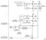
I mainly had in mind an output stage like the following (from NXP LPC series mcu) which disable the high side mosfet in open drain mode

LPC_output_stage.gif

Alex
 

So there are devices that have an open drain mode where the user can either enable the upper side or the lower side mosfet?
No I don't think so. But basically any tristate push-pull output stage can be used this way. Dedicated open-drain mode, as you report it for the NXP processor has a special purpose because it e.g. allows an UART to operate in open drain mode. But in software bit-banging, you can also implement an active high (PMOS) open drain stage.

In case of FPGAs, where everything is user logic, you can implement active low open drain or active high open drain at will, by a simple HDL expression:

Code:
active_high_od_out <= '1' when active = '1' else 'z';     
active_low_od_out <= '0' when active = '1' else 'z';
 

Yes I was thinking that what you describe could emulate a high or low open drain switch.

Now to go back to the question of shaiko you can't expect enabling any of the pull up/down resistors to automatically invoke the opposite side output driver device, you have to specifically turn the device you want on with your code.
You can have a pullup and force through the code the output to either 0, 1 or Z and it's the same with the pull down resistor.

Alex
 

No I don't think so. But basically any tristate push-pull output stage can be used this way. Dedicated open-drain mode, as you report it for the NXP processor has a special purpose because it e.g. allows an UART to operate in open drain mode. But in software bit-banging, you can also implement an active high (PMOS) open drain stage.

In case of FPGAs, where everything is user logic, you can implement active low open drain or active high open drain at will, by a simple HDL expression:

Code:
active_high_od_out <= '1' when active = '1' else 'z';     
active_low_od_out <= '0' when active = '1' else 'z';

Another question
FvM,
What will be the result of the following actions:

1. First : define in code -- some_output <= '1' when some_condition = '1' else '0' ;
2. Second : set a pullup resistor on the "some_output" pin using the GUI tool.
3. compiling

What will be the end result ?
A push pull output or an open drain ?
 

Status
Not open for further replies.

Part and Inventory Search

Welcome to EDABoard.com

Sponsor

Back
Top