Continue to Site

Welcome to EDAboard.com

Welcome to our site! EDAboard.com is an international Electronics Discussion Forum focused on EDA software, circuits, schematics, books, theory, papers, asic, pld, 8051, DSP, Network, RF, Analog Design, PCB, Service Manuals... and a whole lot more! To participate you need to register. Registration is free. Click here to register now.

LCD doesn't Initialize in 4-bit mode

Status
Not open for further replies.

motif

Newbie level 4
Joined
Dec 4, 2011
Messages
6
Helped
0
Reputation
0
Reaction score
0
Trophy points
1,281
Activity points
1,362
Hi All,

From last couple of weeks I am trying to get my LCD JHD162A initialized in 4-bit mode but no success. In default 8-bit mode it seems to be working fine.

I did below experiment to verify that 8-bit mode works fine.
After power-up (default 8-bit), as a part of initialization I just send instruction 0x0F to enable display and then I send data bytes. With this I get what is shown in LCD_init.png (in 8-bit mode). With this it appears that there is no connection related issue between micro-controller and LCD.

Problem comes when I try it for 4-bit mode. I have almost tried all permutation and combinations but it never moves into 4-bit mode. Delay specified in code are in seconds and whole program takes 2-3 minutes to execute.

I have also put large (330uf) cap between power-gnd LCD pins to avoid reseting of LCD and going to default mode due to spikes (which I was not expecting).

In this mess I even tried replacing LCD, but observed same behavior with another one.

I am following JHD162A.pdf and HD44780U which people say compatible with JHD162A displays. I am not sure!!!

I have reduced the code to do initialization and print some characters. The initialization is controlled by define //#define INIT8BIT. If this define is present, it will initialize in 8-bit mode (just enabling display) else in 4-bit mode.

I didn’t want to re-invent the wheel and also tried drivers present open-forums, but they didn’t work (e.g Flex LCD driver).

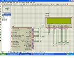
Feel free to ask any other information required, I can re-check anything doubtful. Attaching required code and schematic.

I will really appreciate if people can provide some directions. I am totally lost here..

Regards,
Sandy


## Attached LCD_files.zip contains code, ucontroller to LCD connections and output image.


Here are more details..

LCD : JHD162A
Vcc : 3.30 V
Vee : Grounded.
micro-controller : 16LF727
clock : Internal oscillator.

Pin connections :
#define LCD_DB4 PIN_A3
#define LCD_DB5 PIN_A4
#define LCD_DB6 PIN_A5
#define LCD_DB7 PIN_E0

#define LCD_RS PIN_A0
#define LCD_RW PIN_A1
#define LCD_E PIN_A2

////// debug LEDS
#define GREEN_LED PIN_A6
#define RED_LED PIN_A7
 

Attachments

  • LCD_files.zip
    30.5 KB · Views: 123

It does not mean that life ends if you fail to put some character on LCD in 4 bit mode. Check the link:- 4-Bit LCD | the path
4bit mode LCD routines are available.
 

I inspected the code and didn't find an obvious fault. I agree, that the 8-bit mode test seems to suggest correct interface operation. Of course the delays should reduced to the order of magnitude suggested by the datasheet, but this point shouldn't change the behavior.

As a next step, I would trace code execution with a debugging adapter in MPLAB. By the way, what's the used CCS C version?
 

motif said:
Problem comes when I try it for 4-bit mode.

This is your initialization routine:

Code:
void init_4_bit_mode()
{
///### initilize as per data-sheet.
lcd_send_nibble(0x30);

//### send initial function set as still LCD is in 8-bit mode.
lcd_send_nibble(0x20);

//### send function set again,  4-bit mode, 2 line LCD , JHD162A
lcd_send_byte(0x28);

//### turnon display, cursor, blink-mode
lcd_send_byte(0x0F);

//### Clear display 
lcd_send_byte(0x01);
//### Entry mode, increment, shift=0
lcd_send_byte(0x06);

}

It seems strange that you send nibbles at the first 4 commands. Why not bytes?
 
Last edited:

Although the lcd_send_nibble() routine is somewhat unusual with it's right shift, the procedure is exactly reproducing the suggested initialization by software in the HD44780 datsheet. You need to think about the different interpretation of commands in 4-bit and 8-bit mode to understand, why it's exactly done this way.

P.S.: A link to the datsheet for reference https://inst.eecs.berkeley.edu/~cs150/Documents/hd44780u.pdf
 
Last edited:

FvM said:
Although the lcd_send_nibble() routine is somewhat unusual with it's right shift, the procedure is exactly reproducing the suggested initialization by software in the HD44780 datsheet.
Just checked the datasheet, the initialization procedure includes nibbles for the first bytes.
 

Initialization by software is intended to reinitialize the module out of any possible state, which may be
8-Bit mode
4-Bit mode, ready for command
4-Bit mode in the middle of an abrupted two nibble cycle, waiting for another nibble write.
 

Sir, May I humbly ask you one question?

Apart from HD44780 datsheet, seperate JHD162A datasheet is also available. Seeing them one question came to my mind. Mr. Motif has used 3.3 volt supply(according to the picture). So, what will be the impact of that on read/write timings when the supply voltage is less than 4.5volt.
 

Timing at 3.3V is usually a bit slower. By now, the code has delays beyond any reasonable timing requirements. Thus timing can't be an issue.
 

My understanding is that after power-on, LCD will be in its default 8-bit mode. Hence initial data is sent assuming device in 8-bit mode and later after mode-switch with 4-bit mode. If functions nomenclature is creating confusion, sorry for that. Kindly refer code below..

The delays are so huge that I can even observe specific transactions with multimeter. I am not sure what else can be tried for timing concern.

CCS C version is V4.0

Can any one kindly confirm if this devices (JHD162A) has worked for him/her in 4-bit mode? Or need any hardware setting (shorting/soldering pads at back etc..)


Code:
void lcd_send_byte(int8 n)
{

send_nibble(n >> 4);
send_nibble(n & 0xf);
}


void lcd_send_nibble(int8 n)
{
   send_nibble(n >> 4);
}

void send_nibble(int8 nibble)
{

 output_bit(PIN_A3, ((nibble & 1)));
 output_bit(PIN_A4, ((nibble & 2) >> 1)); 
 output_bit(PIN_A5, ((nibble & 4) >> 2));   
 output_bit(PIN_E0, ((nibble & 8) >> 3));   

 delay_ms(delay_val);
 output_bit(LCD_E, 1);
 delay_ms(delay_val);
 output_bit(LCD_E, 0);
 delay_ms(delay_val);
}
 

i m new in pic ,,,,i m writing the code hi-tech and C.
i trying to make the program for LCD in 4 bit mode,,,,,any body help me,,,,
here is my code....................

//////////////////////////////////////////////////////
///////////////////// 4 BIT LCD //////////////////////
/////////////////////////////////////////////////////
#include<pic.h>
#include <htc.h>
__CONFIG(0x3f32);
#define _XTAL_FREQ 4000000


#define nop asm("NOP")
#define LCD_RS RC0
#define LCD_EN RC1
#define LCD_PORT PORTB //D7-D4
#define LCD_PULSE() ((LCD_EN=1),(LCD_EN=0))

void pic_init(void);
void lcd_init(void);
void lcd_string(const char *s);

void lcd_data(char d);
void lcd_cmd(char c);

main()
{
pic_init(); //initialize PIC
lcd_init(); //initialize LCD
lcd_cmd(0x82);
__delay_ms(10);
while(1){
//lcd_data('F');
//lcd_data('Z');
lcd_string("-FAWAD-"); //display string
}
}

void pic_init(void)
{
PORTB=TRISB=0;
PORTC=TRISC=0;
}
/* initialise the LCD - put into 4 bit mode */
void lcd_init(void)
{
__delay_ms(15); //delay for LCD Power Up
lcd_cmd(0x28); //function set 4 bit
__delay_ms(15);
lcd_cmd(0x0C); //display on/off control
lcd_cmd(0x81); //Set cursor position (DDRAM address)(0x80+addr)
__delay_ms(15);
lcd_cmd(0x0E); //Turn on visible underline cursor(display off)
//__delay_ms(15);
lcd_cmd(0x06); //entry mode set
//lcd_cmd(0x01);
}

/* write a byte to the LCD in 4 bit mode */

void lcd_cmd(char c)
{
LCD_PORT=(c&0xF0);
LCD_RS=0; //for cammand
LCD_EN=1;
asm("NOP");
LCD_EN=0;

LCD_PORT=(c<<4);
LCD_RS=0; //for cammand
LCD_EN=1;
asm("NOP");
LCD_EN=0;
}
void lcd_data(char d)
{
LCD_PORT=(d&0xF0);
LCD_RS=1; //for write the charactor
LCD_EN=1;
asm("NOP");
LCD_EN=0;

LCD_PORT=(d<<4);
LCD_RS=1;
LCD_EN=1;
asm("NOP");
LCD_EN=0;
}

void lcd_string(const char *s)
{
while(*s)
lcd_data(*s++);
}
 

fawadbutt said:
i trying to make the program for LCD in 4 bit mode

What is the problem you are facing?
I haven't read your lcd's datasheet, but initialization of an LCD usually starts with lcd_cmd(0x30); 3 times in a row and each of these commands is followed by a delay of tenths of milliseconds. Please double check the initialization procedure on both commands and delays from the datasheet and compare it with your lcd_init function.
 

my 8 bit lcd code is running lcd_cmd(0x38) ...but when i write the code with 4 bit lcd ,,,,,lcd_cmd(0x28) with masking...i m testing the code in protues7.7....nothing on lcd,,,i dont understand where is problem. 7.7.JPG
 

Since I got it working, I have never edited the initialization routine of the lcd. I always use 4-bit mode.

Code:
void lcd_init (void)
{  
  Delay_ms(50);
  LCD_cmd(0x30);
  Delay_ms(10);
  LCD_cmd(0x30);
  Delay_ms(10);
  LCD_cmd(0x30);
  Delay_ms(10);
  LCD_cmd(0x20);  //4 bits bus
  Delay_ms(10);
  LCD_cmd(0x28);
  Delay_ms(10);
  LCD_cmd(0x08);
  Delay_ms(10);
  LCD_cmd(0x01);
  Delay_ms(10);
  LCD_cmd(0x06);
  Delay_ms(10);
  LCD_cmd(0x0C);  //blink off
  Delay_ms(50);
}

Hope this helps to make it work too! :wink:
 
alexxx,,, thanx for helping me....
but
my lcd initializing routine,,,,,,,,
void lcd_init(void)
{
__delay_ms(20);//wait for lcd power up
lcd_cmd(0x03);
__delay_ms(5);//wait
lcd_cmd(0x03); //again
__delay_us(200);//wait
lcd_cmd(0x03); //one more time
__delay_us(200);//wait
lcd_cmd(0x02); //to enable four-bit mode
__delay_ms(5);//wait
lcd_cmd(0x28);//function set (4-bit,2 line)
lcd_cmd(0x08);//don't shift display,hide cursor
lcd_cmd(0x01);//clear and home display
lcd_cmd(0x06);//move cursor right
lcd_cmd(0x0C);//display on
}
now its work on protues ,,but not work in real circuit,,,,,circuit is tested ......nothing display on my lcd(EC1602J) ...where i m wrong...!, :(
 

fawadbutt said:
now its work on protues ,,but not work in real circuit
OK, you didn't specify that. :smile:

If it is the exact same circuit with proteus, then there must be a bug with the board. A cut wire, a wire short circuited with another one or something like that. Start with this. Verify all your lcd connections with the multimeter. Then if you have a debugger, start giving 0s and 1s from the program and see if those signals are actually reaching the lcd pins succesfully.
 

same circuit is running on 8 bit lcd,,,,, :(
if you think no problem in my code,,,,,than surely problem in my hardware,,plz one more time recheck my code,,,i m very thank ful to you...and i m checking my hardware ....
 

fawadbutt said:
if you think no problem in my code
If the exact same circuit and code are running in the exact same board with 8-bit mode, then the possible problems could be:

1) lcd_init() or lcd_data() or lcd_cmd().
2) Make sure that all 4 lines D0, D1, D2, D3 are constantly kept grounded.

I will look into your code tomorrow.
 
thanx Alexx,,my problem has solved ,,,,
the problem is D0,D1,D2,D3, i have disconnecting the these pins to IC,,,,the code is working in real Hardware,,
next step i want to run RTC(DS1307) with I2C Protocol,,,if i have facing the problem ,i m start the new Thread,,,,,again Thanx :D
 
  • Like
Reactions: alexxx

    alexxx

    Points: 2
    Helpful Answer Positive Rating
Finally got my LCD working...

Issue was with operating voltage, JHD162A doesn't work with 3.3V, it needs 5V.

Thanks Everyone..

Regards,
Sandy
 
Last edited:

Status
Not open for further replies.

Similar threads

Part and Inventory Search

Welcome to EDABoard.com

Sponsor

Back
Top