motif
Newbie level 4

Hi All,
From last couple of weeks I am trying to get my LCD JHD162A initialized in 4-bit mode but no success. In default 8-bit mode it seems to be working fine.
I did below experiment to verify that 8-bit mode works fine.
After power-up (default 8-bit), as a part of initialization I just send instruction 0x0F to enable display and then I send data bytes. With this I get what is shown in LCD_init.png (in 8-bit mode). With this it appears that there is no connection related issue between micro-controller and LCD.
Problem comes when I try it for 4-bit mode. I have almost tried all permutation and combinations but it never moves into 4-bit mode. Delay specified in code are in seconds and whole program takes 2-3 minutes to execute.
I have also put large (330uf) cap between power-gnd LCD pins to avoid reseting of LCD and going to default mode due to spikes (which I was not expecting).
In this mess I even tried replacing LCD, but observed same behavior with another one.
I am following JHD162A.pdf and HD44780U which people say compatible with JHD162A displays. I am not sure!!!
I have reduced the code to do initialization and print some characters. The initialization is controlled by define //#define INIT8BIT. If this define is present, it will initialize in 8-bit mode (just enabling display) else in 4-bit mode.
I didn’t want to re-invent the wheel and also tried drivers present open-forums, but they didn’t work (e.g Flex LCD driver).
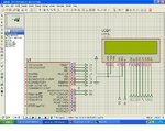
Feel free to ask any other information required, I can re-check anything doubtful. Attaching required code and schematic.
I will really appreciate if people can provide some directions. I am totally lost here..
Regards,
Sandy
## Attached LCD_files.zip contains code, ucontroller to LCD connections and output image.
Here are more details..
LCD : JHD162A
Vcc : 3.30 V
Vee : Grounded.
micro-controller : 16LF727
clock : Internal oscillator.
Pin connections :
#define LCD_DB4 PIN_A3
#define LCD_DB5 PIN_A4
#define LCD_DB6 PIN_A5
#define LCD_DB7 PIN_E0
#define LCD_RS PIN_A0
#define LCD_RW PIN_A1
#define LCD_E PIN_A2
////// debug LEDS
#define GREEN_LED PIN_A6
#define RED_LED PIN_A7


