Vermes
Advanced Member level 4
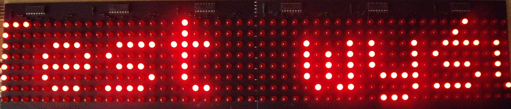
LED matrix with 2 modules 8*24 connected together, had mounted column drivers on 74HC595, and a place for mounting Atmega8 processor or vertical compatible decoder for lines and power transistor on the bottom.
Assumptions:
- using the LED matrix 8*48
- the driver should be made based on AVR microcontroller
- the driver should be equipped with:
- complete power module and lines control module
- real time clock
- thermometer
- non-volatile EEPROM to store the texts and “animation program”
- possibility of programming “animation” via UART/RS232 from a computer
Description
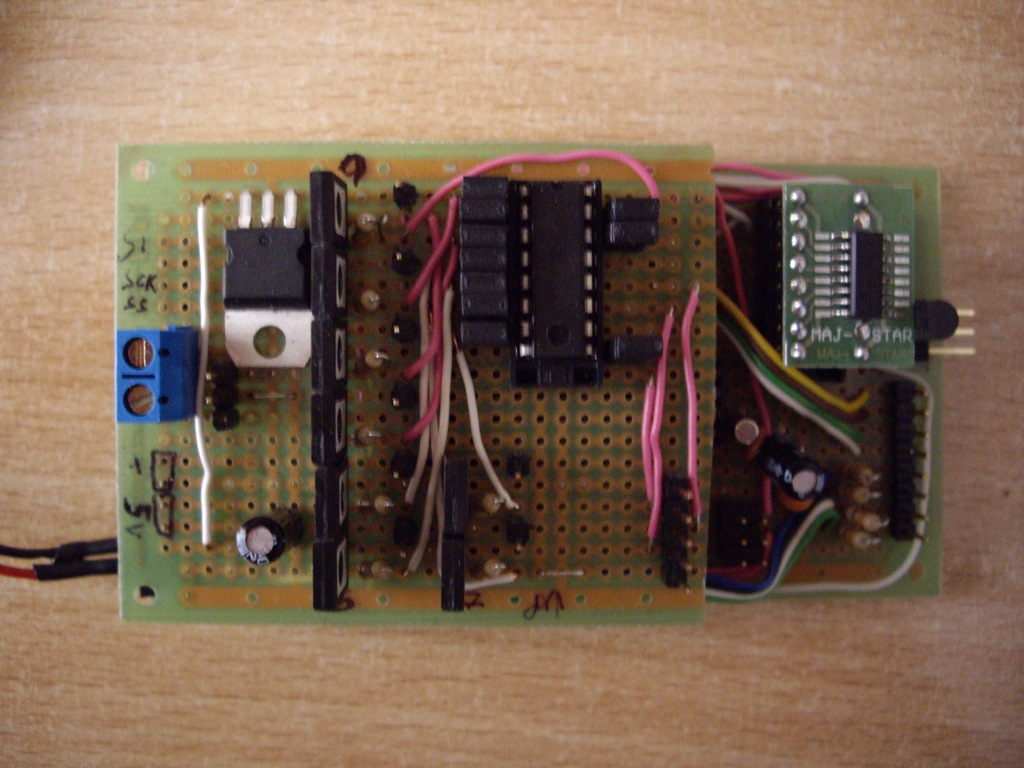
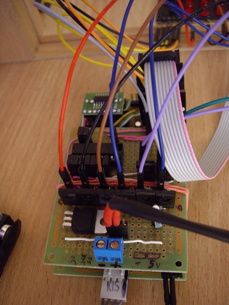
The whole project consists of 3 parts: matrix, “high voltage” and logic part of the controller.
Matrix
Dimensions: 8*48 pixels, 490*120mm.
Controller of columns: six 74HC595 circuits connected in series with a common exit “Latch Enable”.
Recommended voltage of the diodes supply (pulse): 7,5V.
Place for the primary control system – not used – instead of that, pin connector to the controller of the rows and columns.
Driver - “high voltage” part
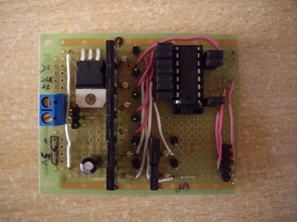
The driver (because of the place on the universal boards) was divided on two separate parts. The first part contains:
Voltage stabilizer: 7805 – to power the second board and 74HC595 circuits – supply voltage of the whole board is 7,5V directly fed to the collectors of the transistors, hence after 7805 circuit, voltage is slightly lower than 5,0V, but it is fully sufficient for the correct operation of all.
Power connector: ARK and HEADERS to the AC
Driver lines: 74HC595 in series with the connector plugged in to the drivers of correct columns on matrix – so the whole matrix is controlled by only 4 pins.
Transistors to drive rowa (8 pieces): BD679A
Connectors for connecting the drivers of the columns, pins of the rows on matrix and power supply of the driver second board.
Driver – controller
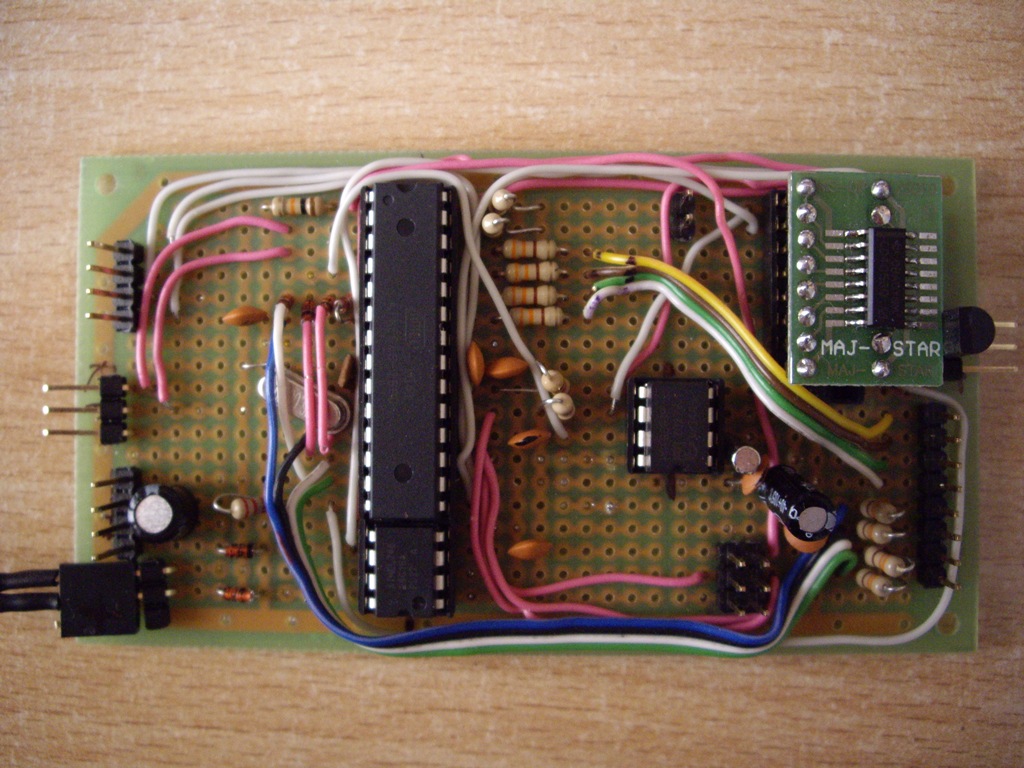
The second part of the driver is the controller. It contains:
Processor: Atmega8 clocked by an external quartz 16MHz.
Real time clock: classic PCF8583
EEPROM: AT24C16
I2C switch: CD4053
The principle is simple – 2 of 3 lines of the system were used. Their common ends are plugged into the processor, and those which can be controlled – according to the PCF8583 (1 pair) and AT24C16 (2 pair). If you want to communicate with the watch, on control lines of the system (stapled together and plugged to a single pin uP) – a high state should be given – if you want to communicate with EEPROM – a low state.
Thermometer: DS18B20 – socket for 1 plate and a connector to plug another one on the cable.
RTC backup system: 2 diodes 1N4148 + connector for connecting the battery packets 2xAA.
Connectors: to connect the “high voltage” board, to connect the back-up batteries, RS232/TTL connector (Rxd, Txd, GND)to program from a computer, ISP connector, 2x connector for DS18B20, connector for matrix keypad 4*4 + diodes 1N4148 to “trigger” interrupts when pressing the button – not used because of the lack of FLASH memory to handle the keypad.
Software
Software was made in C and AvrStudio 4.
Functions supported by the software:
- temperature display for a specified time (1-255s)
- the current time display for a specified time (1-255s)
- static text display (up to 8 characters) for a specified time (1-255s)
- scrolling text of any length (limited by free EEPROM) with adjustable delay of “jump” 1px in the range 1-255ms display
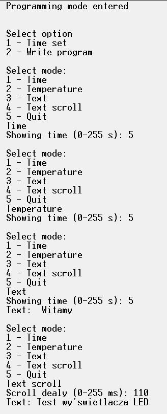
- programming from the terminal RS232 in a simple text menu
- connect the cable RS232/TTL or the USB converter ↔ RS232 to the system
- connect to the terminal in the basic mode: 9600 8-N-1 with the transfer by pressing the button ENTER and then CR+LF (\r\n)
- press the ESC key – enter to the programming mode and the message “PC-CON” is displayed on the matrix
- program by moving around the menu, we are able:
- setting the time
- programming the animation sequence
- finish the possible session of uploading the animation program, to add a marker of return to the address on the beginning of the program, at the end of the entered data
- we can chose one of the options in point 4 once again
- press the ESC button in the main menu, which completes the programming mode – the saved animation starts to execute and we can unplug the cable from the computer and close the connection

Photos:
Videos:
Link to original thread (attachment) – Sterownik wyświetlacza matrycowego LED 8*48