Continue to Site

Welcome to EDAboard.com

Welcome to our site! EDAboard.com is an international Electronics Discussion Forum focused on EDA software, circuits, schematics, books, theory, papers, asic, pld, 8051, DSP, Network, RF, Analog Design, PCB, Service Manuals... and a whole lot more! To participate you need to register. Registration is free. Click here to register now.

Need help with 434MHz receiver circuit explenation!

Status
Not open for further replies.

Kaspars

Junior Member level 1
Joined
Jan 4, 2011
Messages
19
Helped
2
Reputation
4
Reaction score
2
Trophy points
1,283
Activity points
1,511
Hello,

I was wondering, maybe here are some experts in analog circuit design who could help me?

Here is my circuit:
**broken link removed**

This is receiver circuit for 434MHz OOK/ASK modulation. I colored 4 main questions.

1. The basic interest is in L1 * (*1,5turns), there isn't shown coil diameter and wire diameter. I have calculater from Thomson's equation (f = 1/2*pi*sqrt(LC)) that L = 67nH if I use C = 2pF. Is that correct? Also, can I use smd - 67nH? If I understand correct L1 and C4 is needed for tuning receiver to 434MHz?
2. What do this part?
3. Is this pulse modulator with OP? Maybe someone can explain what does it do and what it is?
4. Never seen befor OP Amp circuit like this, is there something missing? Maybe there is feedback needed? And what it do? All I know, that both these OpAmps amplify the signal.

Thanks for any help.

Best regards,
Kaspars
 

At this frequency whatever calculation you do for L1, the circuit needs some tuning to get the desired 434MHz frequency. So, make the circuit and measure the oscillation frequency of T1 (which first job is to be an oscillator), and adjust L1 (diameter, turns, etc) to get 434MHz.
IC1a is an amplifier and a limiter, and IC1b is a trigger and a buffer.
There are a lot of freeware Spice simulators which can show you what is going on with the circuit.

Linear Technology - Design Simulation and Device Models
 
Your questions indicate that you never assembled an UHF receiver.
A 432 MHz "coil" is most often a wire loop, use 1 mm dia. wire and bend a 5-cm length over your finger (8-10 mm dia.). Instead of a 2-pf fixed capacitor, use rAther a 3-10 pF ceramic trimmer. To adjust it you will need a plastic screwdriver.
All connections in your block 1 should be as short as possible, longer than 5 mm is too much for any component.

For illustration how to design UHF circuits, open an old UHF TV tuner and look into it. Or, find ARRL Radio Amateur's Handbook or QST magazine, best from 1960-1970 period.

When you test the receiver, make sure you have a suitable 432 MHZ signal generator. You can use the mentioned UHF TV tuner running nearby (0.5-1 meter away), modulate the 12V DC for it by pulses e.g. at 1 kHz. Such TV tuners start from 470 MHz (tuning capacitor fully closed or tuning voltage ~ 3V). If you can make your receiver detect the ~470 MHz, one small turn of the trimmer will bring the frequency to 432 MHz.
 
Hi,

Thanks vfone, jiripolivka and betwixt for your answers, they were very helpfull :)

vfone I have downloaded your suggested linear Technology Spice simulators and will test it soon (Usually I use OrCAD PSpice simulators).

jiripolivka you are right, I have nevar built any UHF receiver/transmitter so my expierence is very poor, that's why I really appreciate any recommendations/suggestions/instructions in this field.

First of all I would like to inform, that I have built 434MHz OOK Transmitter. Here is circuit:
**broken link removed**

And here you can see how I made it (Used SAW resonator 434MHz):
**broken link removed**

Input signal is asynchronous binary signal with amplitude ~5V (Red line). When I use oscilascope before antenna I get this (blue line):
**broken link removed**

When I use Spectrum Analyzer I get this:
**broken link removed**

Channel power is about -30dBm, that's about 1uW.

So my first question is:

1. How can I increase channel power?

After that I have made receiver (circuit shown in my first post), here is picture:
**broken link removed**

At the antenna output I get this (blue line), and received signal amplitude is ~50mV:
**broken link removed**

So now I have 1mm copper wire, I will try to make L1 (From this site: **broken link removed** I calculated, that I need coil diameter - 8mm, length - 5mm and turns - 3), also I have 3-10p trimmer so I will try to tune it on desired frequency.
Next question is how to measure L1 inductance? I used L1 like this:
**broken link removed**

2. Can I use it? Or I need to make it from copper?

Also I noticed, that 17cm antenna is too big, and decided to make transmitter/receiver with 868MHz or 2.4GHz.
3. Maybe someone have some circuits for 868MHz or 2.4GHz transmitter/receiver? Can I make it the same I did for 434MHz just changing some components?

Yes I know there are a lot of 2,4GHz modules, but they all are for sychronous systems, but my input signal is from Time encoding Machince (TEM) which is asynchronous, so building transmitter/receiver is difficult.

Thanks for help.

Best regards,
Kaspars
 
Last edited:
  • Like
Reactions: ggmssr

    ggmssr

    Points: 2
    Helpful Answer Positive Rating
So now I have 1mm copper wire, I will try to make L1 (From this site: **broken link removed** I calculated, that I need coil diameter - 8mm, length - 5mm and turns - 3), also I have 3-10p trimmer so I will try to tune it on desired frequency.
Next question is how to measure L1 inductance? I used L1 like this:
**broken link removed**
2. Can I use it? Or I need to make it from copper?

No you cant, thats NOT an air cored inductor, its a ferrite cored inductor :) plus the wire on that inductor is substantially smaller than what
jiripolivka said to you several posts back (1 mm diam wire and preferably make it enamelled wire)

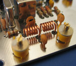
this is what air cored inductors look like.....

attachment.php
see the 2 copper wire spirals ~ 6 turns each


Also I noticed, that 17cm antenna is too big, and decided to make transmitter/receiver with 868MHz or 2.4GHz.
3. Maybe someone have some circuits for 868MHz or 2.4GHz transmitter/receiver? Can I make it the same I did for 434MHz just changing some components?

Yes I know there are a lot of 2,4GHz modules, but they all are for sychronous systems, but my input signal is from Time encoding Machince (TEM) which is asynchronous, so building transmitter/receiver is difficult.
Thanks for help.
Best regards,
Kaspars

for you using modules is the only way, it requires substantial experience to work with 2.4GHz RF, Even 868MHz would probably be quite a challenge. very small surface mount components and some delicate soldering.

There are plenty of 434 MHz antennas available that are substantially smaller than 17cm .... namely the compact "rubber duckie" style that are used on handheld radios in that frequency band

cheers
Dave
 

Attachments

  • eme44b2.jpg
    eme44b2.jpg
    26.6 KB · Views: 390
Hi everybody,

I have changed my circuit and added coil with 1mm wire, coil diameter - 8mm, length - 5mm (From inductor calculator), also added ceramic trimmer, here you can see it:
**broken link removed**

Also I changed my SMD antenna to 17cm wire and got at receiver more powerfull signal (from 1uW to 5uW (u - micro)). Her you can see how looks my signal when I add osciloscope to my antenna:
**broken link removed**

Like you can see from picture (blue line) amlitude has increased from 50mv to 250mV, but also there appear some offset (~1V). So still there is actual question about, how to increase transmitters power? And Why there is an offset, and how you suggest to take it off? (With capacitor?)

Also still actual question is how to make SAW resonator based transmitter/receiver with 2,4GHz resonator (**broken link removed**)?

Also I don't understand how work in receiver IC1a? Non-inverting amplifier look like this:
**broken link removed**

But in IC1a there is two inputs the same, maybe it's differential amplifier? Please someone explain me.

Also IC1b looks incorrect, does it need to look like this:
opAmpBuffer.jpg


Maybe someone can explain how this opamp works.

Also there isn't shown Voltage that is required, so I use Vcc=+5V. Maybe there is needed something other? For Op Amps I use +5V ang GND.

Also I would like to know if I can use 2uH2 smd inductor (reciever circuit) Link? Maybe I need to use coil too?

I tried to tune my receiver, but don't understand how to do that correctly. Maybe someone can explain me? I connected my oscliloscope to circuit and watched for frequency, but it was floating. I tried to change C4 with trimmer, then a little changed amplitude for received signal. at the output of loop I got the same I have in antenna output. Please give a detailed information.

Please if someone know answers for my questions, please help me.

Best regards,
Kaspars
 
  • Like
Reactions: ggmssr

    ggmssr

    Points: 2
    Helpful Answer Positive Rating
Dear friend:

I think you are trying to do too many things at once.

1. It is quite difficult to measure inductance below 1 uH and almost impossible below 0.1 uH=100 nH. All connections to it take part.
2. I have achieved my experience by doing experiments; I can see that you are trying, too. You have good test instruments; I mostly used a grid-dip oscillator up to ~1 GHz, and quite successfully.
3. Your coil of 3 turns with a trimmer I think can resonate rather at ~150 MHz. The SMD coils are usually not good in resonant circuits. My resonant circuit in a superregen receiver like yours was a half-turn coil of 1-mm dia. wire, bent over my finger; with a 3-8 pF trimmer I could tune it to 432 MHz. The transistor and other components also take part in it. On your spectrum analyzer you could also see how the frequency of your transmitter moves when your hand gets close.
4. Connecting an oscilloscope probe to your TX or RX resonant circuit changes strongly the frequency as well as the power level. I would rather connect a Ge-diode to the probe, and detect the signal over ~ 5 cm distance. This would affect the oscillators much less.

You started well- by experimenting! Please go on and improve your devices step by step. At 432 MHz you do not need much power to transmit over ~1 km distance, but the frequency of your TX and RX should be adjusted well. Try enclosing the TX and RX into small metal boxes, with only a RF connector (BNC, SMA) for antenna.
To illustrate what you can do: in 1965 with my 432 MHz transistor transmitter generating exactly 5 mW , and a superregenerative receiver and a 9-el Yagi antenna I have achieved a reliable CW communication over 205 km . You can try to do the same.
 
Hi everybody,

First of all, thanks jiripolivka for detailed answers, they are very helphull for me :)

For now I have decided to make 434MHz data comunication, but my next problem is that, I have 10 binary outputs, so I need 10 transmitters to transmit them. If I understand correct, then I can use only ONE antenna for all 10 transmitters. So maybe someone can explain me how can I make 10 transmitters in "one" frequency, so there weren't interference between each channel, more detailed - how can I select center frequency for each channel (deviation)? Is this possible with SAW-based transmitter (describet in my previous posts)? Also please add some design notes, they would be very helpfull.

Thanks :)

Best regards,
Kaspars
 

How about coding the 10 data channels into one? What's the data rate of each channel?
 
How about coding the 10 data channels into one? What's the data rate of each channel?

Hi FvM, thanks for you reply :)

If I had a syncronous binary data then this approach would be great. But I have asynchronous data (I don't use clock (CLK))

Here is picture for better understanding:
**broken link removed**

I have 10 asynchronous outputs to be transmitter. If there is some coding approach for asynchronous data please let me know (I don't want to use CLK). I want all my system asynchronous. So if there is some ideas how to transmit, please let me know.

Best regards,
Kaspars
 

If the asynchronus data follow comply to a known protocol, e.g. UART with a specified baud rate, they can be encoded to a single data steram with higher data rate. Although the effort is higher than for a simple synchronous data, I think it's still preferable to having 10 transmitters or at least 10 subcarriers.
 
If the asynchronus data follow comply to a known protocol, e.g. UART with a specified baud rate, they can be encoded to a single data steram with higher data rate. Although the effort is higher than for a simple synchronous data, I think it's still preferable to having 10 transmitters or at least 10 subcarriers.

If I use UART at the receiving part there is still clock (CLK) and in my application there aren't bits, there is only time moments when binary output change edge from 0 to 1 and from 1 to 0. I need very high accuracy, so I can't use any clk.

If I didn't understand you correctly, please give me some examples and explain me more about your idea. :)

Best regards,
Kaspars
 

Transmiting multichannel data without sync by a common clock is technically not correct but doable.
You do not need 10 complete transmitters but you need 10 subcarriers spread over a wider bandwidth. Then you should decide what modulation type to use (AM, FM, PSK, etc.), then you can combine all modulated subcarriers to a common antenna.
In my opinion the common clock is much simpler, realizable with a set of 7400 or 4000 integrated circuits, or a more modern FPGA.
Separate subcarrier transmitters are more difficult to make and adjust, and you need to develop corresponding decoders/demodulators in receiver.
One of the good solutions is RC model control, offering several precision digital channels. You can translate the frequency from existing 27 or 40 MHz band to 430 MHz by a simple upconverter/dpwn converter.
Another realization is the IR TV/video control system, easy transferable to 430 MHz.
 
If I use UART at the receiving part there is still clock (CLK) and in my application there aren't bits, there is only time moments when binary output change edge from 0 to 1 and from 1 to 0. I need very high accuracy, so I can't use any clk.
I expected in fact UART like asyncronous data streams, that are basically sampled at discrete times. The "very high accuracy" point will probably contradict the limited bandwidth of the transmitter channel. You should give a rough idea of expected timing accuracy. A single edge can be transmitted over a band limited channel with good accuracy (if noise isn't too severe), but if you have two consecutive edges, the limited bandwidth will cause interpendence of both events.

As jiripolivka mentioned, the subcarrier solution involves a considerable effort. I'm under the impression, that an all-digital solution (digitizing the asynchronous events, combining them in a suitable protocol, transmitting them through a digital modulation method) would be rather state-of-the-art.

If you even want to go for multiple subcarriers, you should check the available bandwidth in the band of interest.
 
Hi all,

Can I ask why the T1's base don't short to ground for radio?
Isn't it a common base oscillator?
 

Hi jiripolivka and FvM :)

Thanks for you answers and sorry for my delay. I didn't have components to test all system futher. In this time I was tying to build an 2,4GHz SAW based transmitter and have great success. But I still have a problem with multichannel. Ofcourse I need 10 subcarriers, I was wondering can I just change my SAW resonator with parallel LC contour and use trimmer to adjust each transmitter to different frequency? (Transmitter schematic you can see in above posts)
 

Dear Kaspars:

As you apparently decided to make ten separate transmitters, please be aware you will also need ten separate receivers. Antennas can be used one for all ten devices by coupling.
Using SAW resonators sounds good but SAW filters are lossy (18 dB typ.) and it is difficult to get ten filters with ten different frequencies at 2.45 GHz. Tuning is not possible by external capacitors, you would only degrade the response.
You could make tuned LC resonators and filters by lumped elements but at 2.45 GHz, the best solution is to use coaxial lines or microstrip.
In my experiments I preferred to use coaxial quarter-wave resonators in a square cavity like in UHF TV tuners. This would work at 2.45 GHz, but I never tried to operate ten channels together. This may be rather tricky.
To start with your system, maybe I would suggest to start at 434 MHz or 910 MHz where RF circuits are easier to make and adjust. Later you could try the final 2.45 GHz band. Your transmitter should not radiate out of this band, to prevent interference.

I still think that using a higher-frequency clock and integrate your 10 channels on a common carrier could be easier to do. How fast are your signals? If they are like ~10 kHz, you can digitally modulate a 1 or 10 MHz clock subcarrier; also decoding is easier.

RC model airplanes utilize a very well proven digital multicarrier technique which works. You can simply move to higher data rate with existing circuits.
 
Hi Jiripolivka and everybody :)

Thanks for your answer :) I have decided to make 434mhz transmitter but my main problem is to get 20 different frequencies. If I understand correctly then my center frequency is choosen by SAW resonator frequency? I tried to change transmitters capacitors (C3, C4) and coil (L1) values:
**broken link removed**

I was inspired by this link: Saw Transmitter Circuit

With these value changes I could get little center frequency deviation. But I want to get 20 different center frequencies. For example f1 = 400MHz, f2 = 410MHz, f3 = 420MHz ect., because occupied bandwidth for one channel is ~4MHz.
So The question is how to deviate SAW resonator center frequency?
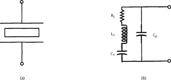
If it isn't possible, then how can I make oscillator/resonator by my self? Can I use just LC contour? Do I have to choose C and L values from Thomson's formula (f = 1/2*pi*sqrt(L*C))? I tried to do that with C = 2p and L = 68nH, but it doesn't work. Any suggestions?
fig16-1.jpg

Note: I Used only Ls and Cp.

Thanks :)

Best regards,
Kaspars
 

Dear Kaspars:
I think your effort is admirable but please consider the following:
1. The 434 band has a limited bandwidth and is shared with other users. You may not be legally allowed to fill the band with your ten channels.
2. You never indicated what signals you need to transmit through your 10-channel system. If they are slow pulse trains, I would rather advise to try again the digital method on a single carrier. If they are fast pulse trains, then you will need for each channel an appropriate bandwidth which must be filtered at TX and RX, to achieve a reasonable mutual isolation,'
3. SAW filters are created as a thin film on LiNBO or similar substrate, and are not tunable by external components. Any reactance connected to either side will affect the response but not the center frequency. I have advised you earlier that at UHF, coaxial filters are easy to make and tune. The combining ten filters will be tricky- you would need some amplifiers and attenuators to make sure filter tuning stays fixed when you tune their neighbors.
4. Using ten "wide" filtered bands side by side requires a careful frequency planning. If you can fit into 1-2 MHz with all, you can possibly use the 434 MHz band. If the complete bandwidth is wider, then converting it to 2.45 GHz or higher may be required.
5. First try to make well running two-channel system. With it you learn the basic problems, and you can decide if to go to ten channels.
 

Status
Not open for further replies.

Similar threads

Part and Inventory Search

Welcome to EDABoard.com

Sponsor

Back
Top