Continue to Site

Welcome to EDAboard.com

Welcome to our site! EDAboard.com is an international Electronics Discussion Forum focused on EDA software, circuits, schematics, books, theory, papers, asic, pld, 8051, DSP, Network, RF, Analog Design, PCB, Service Manuals... and a whole lot more! To participate you need to register. Registration is free. Click here to register now.

50hz clock cycle from ac for timer 0 :p

Status
Not open for further replies.

d@nny

Full Member level 5
Joined
May 28, 2011
Messages
246
Helped
11
Reputation
22
Reaction score
11
Trophy points
1,298
Activity points
3,238
I want to this

220 volt ac

100K resistance on live wire
100K resistance on ground wire
short them with 2.2k resistance after 100k
make the ground wire ground with pic vss pin
attach the live wire with timer0 directly orrrr
attach the live wire with base of npn transistor with 2.2K resistance and the collector of npn with 5v and the emitter with timer0
any problem here????????
 

Capture.JPG

This is good or need to attach a npn transistor on TOCK1 pin
 

View attachment 60775
This is good or need to attach a npn transistor on TOCK1 pin

Hi D@nny,

Do you really think you can get away with apply a 220V AC signal across the Vss and TOCK1 pins?

Or are you just trying to come up with another inventive way to fry another PIC?

BigDog
 

I dont wana fry another as i have got this very hardly. Thats why i want to discuss it first. What do u think it is good idea or not?
(This is not related with first one can i sense the presence of ac with out using any transformer as attacthed bridge and 1 uf capacitor than npn transistor????)
 

What do u think it is good idea or not?

Not! Very bad idea.

First of all even if you could reduce the AC voltage down to 5V AC, you still cannot apply a negative voltage to a PIC's pin.

Why not implement a zero crossing detector? This would generate a pulse as the AC signal cross 0V level.

This technique is commonly used in AC dimmer circuits.

BigDog
 

whats about this to sense presence of ac signal and get 50hz clock signal also? the npn transistor can be used or 5.1v zener can also add on pic pins ?
Capture.JPG
 
Last edited:

if use half bridge rectification?

Not necessarily, there are several different design variations available.

**broken link removed**


You have to keep in mind that the PIC's pin are high impedance, so 100K ohms is not high enough.

Here's a similar design as yours, however it has more appropriate resistor values:

**broken link removed**

You may have to take into account the next design is from AVRs which I believe has a high tolerance to negative inputs on pins.

AVR182: Zero Cross Detector

Motor Control Using Triac

BigDog
 

Yes, good idea Alex.

I was actually looking for an example of an Optocoupler, but got distract elsewhere.

Here is one design which uses a Schmitt Trigger Output Optocoupler.

**broken link removed**

BigDog
 
Last edited:

can i use this **broken link removed**
 

Yes if you sufficiently limit voltage and current across the LED of the Optocoupler.

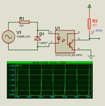
Here is the optocoupler zero crossing design I was looking for early:


BigDog
 
ZC-schema.gif


If i dont use 2n3094 but a diode so that only one cycle emit the led. Is this not a good zerocrossing technique as the npn transistor and a diode can do this?
 

The 2N3904 is just a NPN general purpose transistor used for switching in this case.

I would just find a suitable replacement and not mess with the design.

2N3904 NPN General Purpose Transistor

Just find a transistor with similar characteristics and you should be fine.

BigDog
 

ZC-schema.gif


If i dont use 2n3094 but a diode so that only one cycle emit the led. Is this not a good zerocrossing technique as the npn transistor and a diode can do this?

If you just want to get pulses at the same rate as the mains frequency I don't see the reason to use the more complicated zero crossing circuit.
Do you want a zero crossing detector or just a clock of 50Hz?

Alex
 

If you just want to get pulses at the same rate as the mains frequency I don't see the reason to use the more complicated zero crossing circuit.
Do you want a zero crossing detector or just a clock of 50Hz?

Alex

Currently i just want 50hz clock cycle for mcu
 

The common mode AC will surely turn you r PIC16 to charred carbon .Best way is to put put two nos 1N4148 back to back between the two nos 100K resistors .In addition put a 0.01 poly .400VDC capacitor in series on either leg.The +/- 0.6VAC square wave generated will run the clock after amplification.
Alternately , you can use 5.1VDC zeners in series for generation of biphase 5VDC signals for clocking ..
 

my.JPGd@nny
clock in.JPG

I used this and working well
I think you will help this, this is very easy
 
Last edited:

This will work very well if you go for some adaptor transformer with 5V AC output .
Put a series res. 10K ohm before a bridge so that currents are limited to one/two milliamp.
The bridge will give 1.4VAC for your clock and Transformer shall isolate this from AC mains supply.
Works well.
 

View attachment 60775

This is good or need to attach a npn transistor on TOCK1 pin

You might actually be able to do that. I did one such thing ago. The reason it shouldn't cause a problem is that, the PIC pin has 2 diodes, that clip the voltage to Vcc+0.6v and negative voltage to Vss-0.6v provided the current is limited. In fact this is a common practice in non-isolated circuits such as lamp dimmers, etc

One application is this: ww1.microchip.com/downloads/en/AppNotes/00958A.pdf

Hope this helps.
Tahmid.
 

Status
Not open for further replies.

Similar threads

Part and Inventory Search

Welcome to EDABoard.com

Sponsor

Back
Top