asdf44
Advanced Member level 4

KlausST I didn't really detail the threshold or the output so as shown the output was inverted and it was turning on at ~140V. If specs were AC RMS then obviously that would change by a factor of sqrt(2). And again it needs the full rectifier and should use the output circuit you showed.
But the error stackup is favorable as the zener threshold is probably the biggest contributor. The rest of the circuit contributes about 5V of error or so (coming from the voltage variations in the Vgsoff of the depletion, the forward drop of the opto and the rectifier diodes). So a window of 30V is easy to hit (though the slow operation of the opto is another factor).
Betwixt, those numbers were the allowable limits on the 'ON' threshold, not window comparator numbers.
But yeah that's how its meant to work. An LND150 would also be a good alternative to the IXCP10M90S. The LND150 in SOT223 would be smaller and cheaper which should be ok given that the zeners are eating up a large chunk of the voltage/wattage.
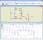
This shows the full rectifier and modified threshold to ~140VRMS (200V DC threshold)


