Continue to Site

Welcome to EDAboard.com

Welcome to our site! EDAboard.com is an international Electronics Discussion Forum focused on EDA software, circuits, schematics, books, theory, papers, asic, pld, 8051, DSP, Network, RF, Analog Design, PCB, Service Manuals... and a whole lot more! To participate you need to register. Registration is free. Click here to register now.

220VAC Input Burning Problem

Status
Not open for further replies.
KlausST I didn't really detail the threshold or the output so as shown the output was inverted and it was turning on at ~140V. If specs were AC RMS then obviously that would change by a factor of sqrt(2). And again it needs the full rectifier and should use the output circuit you showed.

But the error stackup is favorable as the zener threshold is probably the biggest contributor. The rest of the circuit contributes about 5V of error or so (coming from the voltage variations in the Vgsoff of the depletion, the forward drop of the opto and the rectifier diodes). So a window of 30V is easy to hit (though the slow operation of the opto is another factor).


Betwixt, those numbers were the allowable limits on the 'ON' threshold, not window comparator numbers.

But yeah that's how its meant to work. An LND150 would also be a good alternative to the IXCP10M90S. The LND150 in SOT223 would be smaller and cheaper which should be ok given that the zeners are eating up a large chunk of the voltage/wattage.


This shows the full rectifier and modified threshold to ~140VRMS (200V DC threshold)
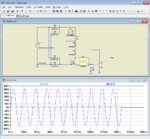
Capture.PNG
 

Thanks for the replies.
If we change the SAFE OFF limit to 20VAC, but instead can we filter the voltage that is produced on the way from source to controller? To make the circuit smaller and cheaper.
 

Not really, the component that keeps it safe is the optocoupler. Once the signal leaves the optocoupler output it is fixed at the level of voltage you supply it with (V2) and does not change appreciably with the input AC voltage. That means you have to make the decision about the AC levels before the optocoupler, not after it.

Your only other option is to intelligently measure the AC using an MCU then opto-couple a 'good/bad' indication to the controller circuits. The problem with using that method is you still have to produce a regulated supply to power the MCU.

Brian.
 

Again, I'll note that using a step-down transformer to isolate the AC and bring it into the MCU's domain is another good option. Once there, a regular cheap comparator can be used. Or it could safely sent to an MCU ADC where the code can implement whatever limits it wants (because its isolated, it can be biased right to the ADCs mid-scale without necessarily needing a buffer amp, though it would need protection such as clamping diodes).


I initially concepted the circuit above for a DC application, hence no transformer. The only other advantage of the opto circuits discussed is that they're completely independent (or can be), which could be a benefit if it's gating a relay or something that's a safety concern.
 

A trick with AC measurement that avoids the buffer amp and offset problems is to use a small isolating transformer and single diode rectifier (or center tapped transformer but not a bridge rectifier) to produce the MCU supply. Then from the 'hot' end of the transformer secondary (rectifier connection) wire a second rectifier and capacitor to ground. That means it looks like you have two identical DC feeds from the transformer, one for the MCU and one for measurement. The MCU uses a big capacitor and regulator in the normal way, the other feed uses a much smaller capacitor, maybe 1uF or less. Across that capacitor you wire a potential divider to keep the voltage at it's tap within MCU ADC range.

The measurement is done like this:
1. the ADC pin is made a digital output and driven low, this discharges the capacitor through the top resistor of the divider to remove any previous peak. Wait a few mS.
2. the pin is then changed to an ADC input so it no longer sinks current. This lets the capacitor recharge to the present AC peak voltage. Wait a few mS.
3. an ADC measurement is taken.

As long as the 'wait a few mS' is more than a few AC cycle periods, the capacitor voltage and hence AC peak measurment will be accurate. Dividing the voltage by 1.414 then adjusting for the scaling factor of the potential divider will tell you the exact AC voltage.

Brian.
 

Status
Not open for further replies.

Part and Inventory Search

Welcome to EDABoard.com

Sponsor

Back
Top