Continue to Site

Welcome to EDAboard.com

Welcome to our site! EDAboard.com is an international Electronics Discussion Forum focused on EDA software, circuits, schematics, books, theory, papers, asic, pld, 8051, DSP, Network, RF, Analog Design, PCB, Service Manuals... and a whole lot more! To participate you need to register. Registration is free. Click here to register now.

coplanar stripline simulation in hfss

Status
Not open for further replies.

acidphreak

Newbie level 3
Joined
Jul 19, 2011
Messages
3
Helped
0
Reputation
0
Reaction score
0
Trophy points
1,281
Activity points
1,312
hello
i'm a novice to hfss please help me..
i'm having problems in designing co-planar stripline in hfss:

1) can't decide upon dimensions since there is no fixed rule linking dimensions and frequency of interest (1-12ghz).

2) the type of excitation to be given is still not clear.

3)since i'm using driven modal so differential excitation is not possible, but there is 2 strips of metal involved here so it would be better to have differential excitation.

4)since this cps does not have any ground plane so it is not of resonating type but still the s11 or s12 etc. graphs show sharp dips at certain frequency (implying it to be acting as a resonating structure!!).

5)its tx in nature so it can't be radiating also.

6)hfss 12 comes with a ε plotting function too, does it implies it is actually plotting the permittivity or it is something else? so for calculating we do not need to extract permittivity from s matrix using matlab??

would anyone b thoughtful enough to give the method to extrct ε from s matrix by matlab??

thanks in advance!!!
 
Last edited:
1) there are tons of literature and TRL calculators for this
2) Waveport
3) Use Driven Terminal...that way you get single ended and differential S Parameters. Driven Modal just returns the modal S parameters.
4) Your return loss will have 'dips' in it if is is any appreciable length relative to the wavelength of interest...read any Microwave text for more info
5) not necessarily true...but another day
6) HFSS plots the 'effective' permittivity of a given mode. I forget whether this is just for the modes or also for the single ended signals. It would seem to only make sense for a mode, but I guess a weighted average can be done to determine the effective permittivity of a given single ended excitation though if difference in gamma is too big and propagation distance large, then this will lose validity as modal dispersion will separate your signals (in time).

Thanks for reply. but i still have some doubts:

a) the calcultr s/w take value for f,epsilon,z(impedance) etc. and give w,s,l etc. in turn and vice versa, but by that logic we can use same dimension for many frequencies, which is not right, cause there has to be some dependency of frequency on dimension. i could not find anywhere any formula or theory linking these two.

b)if you can tell me any relation between these two it would be very helpful.

c) also the dimension of waveport and integration line are a problem(which dimension , where to put the integration line??).

d)if i want to design in 60ghz range how would the dimension of strips would differ from 1-12ghz range??

e) if you could give me a hfss file on cps, it would be immensely helpful.

f)again as i said i m a newbie, if you could tell me while giving integration line we can give different no. of modes, what exactly these modes means(physical significance).

thanks in advance.
 

a) the calcultr s/w take value for f,epsilon,z(impedance) etc. and give w,s,l etc. in turn and vice versa, but by that logic we can use same dimension for many frequencies, which is not right, cause there has to be some dependency of frequency on dimension.

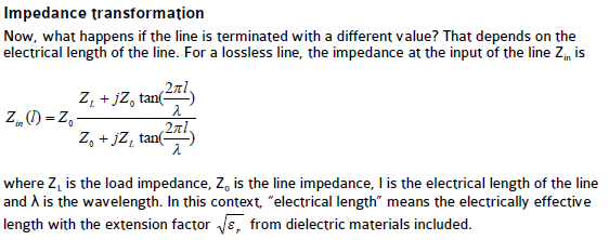
You are wrong. Ideally, the line impedance Z0 is independent of frequency.

The input impedance of a line, which changes with frequency depending on the load impedance, is a different thing.

---------- Post added at 08:55 ---------- Previous post was at 08:50 ----------

54_1312527311.png
 

thanks for reply ....but there still must be some relation between dimension and frequency allowed to travel to travel through cps???
i am looking for that relation or formula. help me please!!

thanks in advance..
 

Status
Not open for further replies.

Part and Inventory Search

Welcome to EDABoard.com

Sponsor

Back
Top