Continue to Site

Welcome to EDAboard.com

Welcome to our site! EDAboard.com is an international Electronics Discussion Forum focused on EDA software, circuits, schematics, books, theory, papers, asic, pld, 8051, DSP, Network, RF, Analog Design, PCB, Service Manuals... and a whole lot more! To participate you need to register. Registration is free. Click here to register now.

Need ATX Power Supply Repair Manual

Status
Not open for further replies.

Strange Problem

Junior Member level 2
Joined
Jul 17, 2011
Messages
21
Helped
4
Reputation
8
Reaction score
4
Trophy points
1,283
Activity points
1,457
Hi,
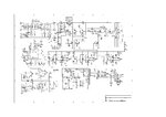
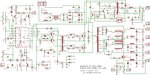
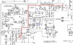
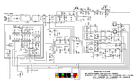
I need a Repair/Service Manual for ATX Power Supply . It will be more helpful if it is a diagram based on Made by China ATX Power supply . Because in my country - China made ATX Power Supply is available .

If anyone have this, please share with me ..........

Thanks .
 
Last edited:
I´m aware that is not the answer you expect, but most of problems related to power supplies are statistically concentrated in switching devices ( IGBT, MOSFET ) or at the Fuse.

+++
 
Do you mean "pin out", rather than "point out?" If pinout, this should help.

If voltages, let me know, I do have a schematic of a typical ATX laying around.

John
 
Thanks Andre for your Reply . Yes you are right . I am facing Switching problem with an ATX PSU . This PSU has burnt out 13007 Transistor and its Base fusing Resistor 10 ohms . I have Replaced them but still it is not starting . I have checked rest all of parts of the PSU Except in Controller section's Resistors . But in Controller section - I am getting 5VSB and 5V PS-ON . But still it does not run . Even I have changed IC TL494 and LM339 also ...... but all the hail ..... It does not listen to me at all . What will I do now ??? Why it is not switching ???
 
Had you attached some load to output ?
A minimal current drain is required to SMPS works.
( I´m asking just to certify )


+++
 
Some ATX Power supply schematics:
 

Attachments

  • ATXpower3.bmp
    2 MB · Views: 386
  • 300W ATX PC POWER SUPPLY.gif
    300W ATX PC POWER SUPPLY.gif
    49.6 KB · Views: 1,418
  • ATX6.jpg
    ATX6.jpg
    1,009.8 KB · Views: 1,053
  • ATX22.PNG
    ATX22.PNG
    45.1 KB · Views: 5,490
  • atx250_sg6105.gif
    atx250_sg6105.gif
    46.3 KB · Views: 1,089
  • ATX win 235.jpg
    ATX win 235.jpg
    386.8 KB · Views: 3,067
  • FSP145-60SP.gif
    FSP145-60SP.gif
    61.1 KB · Views: 1,219
  • iwp300a2.gif
    iwp300a2.gif
    49.9 KB · Views: 841
  • JNC Y-B200-ATX.BMP
    888.8 KB · Views: 305
  • jnc.gif
    jnc.gif
    120.6 KB · Views: 2,640
Ya .... I had tried with also . I attached a ASUS CD-ROM 52X . But no hope .......
 
ATX power supply schematics
 

Attachments

  • ATX2005.pdf
    149.9 KB · Views: 501
  • ATX7500.pdf
    46.1 KB · Views: 445
  • ATX-5400M (Microlab 350W).pdf
    47.3 KB · Views: 376
  • ATX-5400X (Microlab 400W).pdf
    46 KB · Views: 374
  • ATX 2 SCHEM .pdf
    629.3 KB · Views: 441
  • ATX Power Supply HPC-420-302 DF.pdf
    178.1 KB · Views: 417
  • ATX Power Supply Linkworld 200W, 250W, 300W.pdf
    385.8 KB · Views: 447
  • ATX PowerSupply-W-P300.pdf
    213.9 KB · Views: 435
  • ATX_forward_1 PC Power.pdf
    2.9 MB · Views: 537
  • ATX_forward_2 PC Power.pdf
    2.3 MB · Views: 508
ATX power supply
 

Attachments

  • ATX_forward_3 PC Power.pdf
    2.1 MB · Views: 422
  • ATX_half bridge PC Power.pdf
    1.3 MB · Views: 496
  • ATX_Microlab-5400M-2.pdf
    47.3 KB · Views: 291
  • ATX_Microlab-5400X-1.pdf
    46 KB · Views: 276
  • atx_ps300w.pdf
    82.1 KB · Views: 345
  • atx_tap_dtk_3518.pdf
    64.3 KB · Views: 298
  • JNC Computer CO., LTD model LC-B250ATX.pdf
    52.5 KB · Views: 320
  • jnc_model__atx400w_1548.pdf
    905.4 KB · Views: 390
  • jnc_sy-300atx_c5027_atx_power_supply.pdf
    729.3 KB · Views: 369
  • PS2_450W.pdf
    154.4 KB · Views: 428
Thumbs Up dude

---------- Post added at 01:36 ---------- Previous post was at 01:33 ----------

ATX power supply

A lot of thanks mister RF . I have given Thumbs up but How can I give you Points ...
 
ATX power supply
 

Attachments

  • ATX-300P4-PFC.pdf
    32.6 KB · Views: 333
  • codegen_250xa1_cg-07a.pdf
    71.5 KB · Views: 369
  • colors_it_330u_sg6105.pdf
    330.7 KB · Views: 333
  • DEZH_BEZ_OPTRONA_SG1605.pdf
    24.9 KB · Views: 280
  • DPS260EP_1.pdf
    218.6 KB · Views: 344
  • DPS260EP_2.pdf
    132.5 KB · Views: 311
  • DTK_PTP_2038.pdf
    27.1 KB · Views: 281
  • FSP145-60SP.pdf
    64.4 KB · Views: 305
  • IP-P350AJ2-0.pdf
    283.3 KB · Views: 345
  • IW-ISP300AX.pdf
    176.1 KB · Views: 400
ATX power supply
 

Attachments

  • KME_pm-230.pdf
    37.1 KB · Views: 273
  • MaxpowerPX-300W.pdf
    59.2 KB · Views: 313
  • Power_Master_FA_5_2_v3-2.pdf
    133 KB · Views: 329
  • Power_Master_LP-8_AP5E.pdf
    133.2 KB · Views: 327
  • SevenTeam_ST-200HRK.pdf
    145.1 KB · Views: 349
  • SHIDO_ATX-250.pdf
    37.8 KB · Views: 303
  • SUNNY_ATX-230.pdf
    30.7 KB · Views: 321
  • iwp300a2.pdf
    34.1 KB · Views: 283
  • atx_pfc400w.zip
    290.9 KB · Views: 329
  • ATX_DR0183.zip
    182.7 KB · Views: 304
Ok, OK ... Thanks Dude ...... I do not need more Schematic ...... These are enough for me .

But do you have any Repairing Guide or manual ??
 

What about the ''+12V" power supply from the stand-by circuit (usually for a value of 15-25V), to be applied for the driver section, did you measure it? Any voltages on TL494 pinouts?
 

Attachments

  • PC Power Supply Repair.pdf
    580.3 KB · Views: 474
  • CI voltages.JPG
    CI voltages.JPG
    107.2 KB · Views: 5,251
Here is the measurement of Voltage .... Shown in the below Image ....
 

Attachments

  • PSU.GIF
    PSU.GIF
    320 KB · Views: 593

Need to check Q4 & Q5.
Also, to be sure change capacitors C9/C10, check components: R6/R7, R10/R11, D4, D3.

PS: input Power ON = low :smile:
 

Attachments

  • Atx_test 2.GIF
    Atx_test 2.GIF
    37.9 KB · Views: 1,974
I have checked Q4 and Q5 C945 - Both of them are Fine . C9/C10 are 2.2μF/50V - this capacitors seems to be OK . Will I change it though ?? There is no R7 and R11 Resistor . They have only one fusing Resistor 10Ω Which is in Transistor's Base R6 and R10 . But they have used two signal/Crystal Diode in place of one Diode . They are D3/D4 and D5/D6 . I have checked them . They are OK . Still Do I need to change these 10Ω Resistor and D3/D4 and D5/D6 Crystal Diode (1N4148) ??

And yes you are right . PS-ON voltage seems to be low . I measured the voltage and it is 4.8V . But there is no Capacitor with the PS-ON nor any Transistor . Will 4.8V be problem for PS-ON ?? How can I increase the voltage of PS-ON to 5V ??

And one thing we need give attention in the previous Post . That is DTC (Dead Time Control) Voltage of Pin4of TL494 . As it's Datasheet DTC will be 3.3V (Maximum) at Zero Duty Cycle . And OV at Max. Duty Cycle . Here it is showing 3.2V . Is Zero duty Cycle means PS-OFF Condition ??
 

I have changed all those capacitors, Diodes and Transistor with new one . But still the Power supply is not running . What will I do now ??

Please Response ........... I am waiting for your reply ......
 

PS_ON must be grounded for the supply to turn on..

Pleases me to see that the schematic was done on AMIGA :)
 

Wow. lots of SMPS circuits here, but I want to have a circuit diagram of bit higher wattage PSUs, i.e. >= 500W - 1000W. Want to have circuits of dual rail system with almost 40-44A on +12V line. Can anybody have those circuits?
 

Status
Not open for further replies.

Similar threads

Part and Inventory Search

Welcome to EDABoard.com

Sponsor

Back
Top