Continue to Site

Welcome to EDAboard.com

Welcome to our site! EDAboard.com is an international Electronics Discussion Forum focused on EDA software, circuits, schematics, books, theory, papers, asic, pld, 8051, DSP, Network, RF, Analog Design, PCB, Service Manuals... and a whole lot more! To participate you need to register. Registration is free. Click here to register now.

N-Channel MOSFET based H-Bridge

Status
Not open for further replies.

Ashkar

Full Member level 2
Joined
Sep 16, 2010
Messages
131
Helped
2
Reputation
4
Reaction score
2
Trophy points
1,298
Location
India
Activity points
2,207
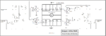
I was designing an N-Channel MOSFET based H-Bridge circuit for my 50Amp D.C. motor,Please look at it and suggest any improvements ,correction or criticism :cool:.
AKA BRIDGE VR1.6 | Flickr - Photo Sharing!
And I also need the charge pump to supply 24v to the high side through available 12v dc supply(pb battery ):arrow:
 

You are using a very low resistor in the collector of the BC546, the collector current will be about 1-2mA , setting this to about 50mA would increase the base current of BD139/140 so that you can get 1-1.5A output.
Also consider to use transistors with higher gain like 2SD882/2SB772
www.unisonic.com.tw/datasheet/2SD882.pdf
www.utc-ic.com/spec/2SB772.pdf
You can also replace BC546 with a mosfet like 2n7000.

I think your gate resistor should be much lower, 47 ohm limits the current to 250mA and you want to achieve fast switching because you have high drain currents.
Also add capacitors very close to the collectors of each BD139/140 to be able to supply the high current pulses fast.
You may need to use some kind of protection for the gate of the upper mosfets because if the 12v power supply is missing for whatever reason then your gates will get 24v which will damage the mosfets.
Also using external diodes across the drain-source of the mosfets would be a good idea.

Alex

---------- Post added at 14:09 ---------- Previous post was at 12:55 ----------

You should also consider using a dedicated high current mosfet driver.
A device like IR2110 can drive the mosfets with higher current, can work with bootstrap to drive the upper mosfet gates correctly and also has protection for the gates.
You may also consider a better mosfet, for example IRL2203, it has slightly lower Rds-on=7m ohm and it is also much easier to drive, the total gate charge is just 60nC (your mosfets has 146nC) so you can get faster switching speed with the same gate current.

Alex
 
  • Like
Reactions: Ashkar

    Ashkar

    Points: 2
    Helpful Answer Positive Rating
WoooooW thats hell lot of Information that I got,Thank you very much for your reply Alex,I would surely implement these ideas And for using ir2203 I was just liked to use my own designes Its kinda fun to develop my own circuit rather buying those of the shelf products Hope you would Understand.
> Would you please supply a schematic for a charge pump and once again thanks a lot.
 

I like to make discrete driver too but I'm handling much lower currents, your output current will be too high so switching speed will be essential to reduce the power consumption on the mosfets (to reduce heat).
If you want to add a discrete bootstrap to generate the higher voltage for the gates of the upper mosfet then the typical circuit would look like this

mosfet_driver_bootstrap.gif

To use bootstrap you need to have constant switching so that the bootstrap capacitor charges, you can't have the bridge working in one polarity for too long

Alex
 

My schematic shows only the high side mosfet with a load, in an H-bridge the lower side mosfet will replace the resistor, the bootstrap capacitor should be connected between the upper mosfet source pin and lower side drain pin (no resistor between them).

Alex
 

I am sorry But i am unable to figure out ,how the circuit is used as a charge pump,can you please elaborate the idea.
 

If you download **broken link removed**, it is described in page 21-22.

Another schematic that may help is this
Bootstrapped Mosfet.PNG
It was uploaded by audioguru in an old post.

When the transistor (ground switch) turns on then the capacitor gets charged to 11.3v through the diode (Vcc - Vf of the diode).
Then when the transistor turns off and the mosfet turns on, the mosfet Source will have 11.9v (almost the same as the drain since the mosfet is conducting), the capacitor will work as a floating power supply and add the 11.3v charge over then 11.9v of the Source, this provides the 23.2v to the gate driver.
It is like having a battery connected from the Source to the gate, it will always provide VSource+Vbattery to the gate.

Alex
 
Last edited:
  • Like
Reactions: Ashkar

    Ashkar

    Points: 2
    Helpful Answer Positive Rating
I got the idea now about the charge pump,and what advancements r necessary in the circuit
 

**broken link removed**
please try this link ,Its also my thread started for the h-bridge,Please try this pump charger and determine for its efficiency and other stuff.
 

Why do you want to use a circuit like this to generate the 24v for the H bridge?
You are using external pulse signal and all that the circuit does is to generate the 24v, then you need another driver to actually take this 24v and drive the gate.
In the bootstrap I have described a capacitor and diode will be enough to generate the 24v and drive the upper mosfet properly, assuming that your bridge is switching so that the capacitor charges.

Alex
 

my problem is that I would be not be switching the circuit frequently.
 

You are using an emitter follower to drive the totem pole, what will be the input voltage of inputs A and B?
And why did you increase the value of the resistor which is now connected at the emitter of BC546 (22k)?

Alex
 

**broken link removed**
Now is the lower side resistors right
 

I have explained in a previous post why the resistor should the much lower.
You didn't answer to my other questions:
You are using an emitter follower to drive the totem pole, what will be the input voltage of inputs A and B?

Alex
 

Oh If I would be using emitter follower then the output would be logic low at the totem pole output,So I had used emitter follower,If in case the input is not connected then it would burn out the power mosfets.
 

Third time:
What will be the voltage at he inputs A and B?
 

I was little confused about the calculations now fixed it's values,Voltages at the input would be 0-4.5v(driven by microcontroller):razz:
 

Attachments

  • aka bridge vr 2.1.png
    aka bridge vr 2.1.png
    113 KB · Views: 187
Last edited:

The problem is not the watts on the resistor, but is you want to calulate them it is P=V*I or P=V²/R or P= i²*R , you don't need to use high watt resistor.
Do you know how much is the output voltage at the emitter when you drive the base with 4.5v?
 

no I don't know?????
Could you please help me out with the mistakes:oops:
 

Status
Not open for further replies.

Part and Inventory Search

Welcome to EDABoard.com

Sponsor

Back
Top