Continue to Site

Welcome to EDAboard.com

Welcome to our site! EDAboard.com is an international Electronics Discussion Forum focused on EDA software, circuits, schematics, books, theory, papers, asic, pld, 8051, DSP, Network, RF, Analog Design, PCB, Service Manuals... and a whole lot more! To participate you need to register. Registration is free. Click here to register now.

2 stages op amp design - help needed

Status
Not open for further replies.

kingmaker

Junior Member level 2
Joined
Apr 3, 2008
Messages
22
Helped
0
Reputation
0
Reaction score
0
Trophy points
1,281
Activity points
1,429
2 stages op amp design

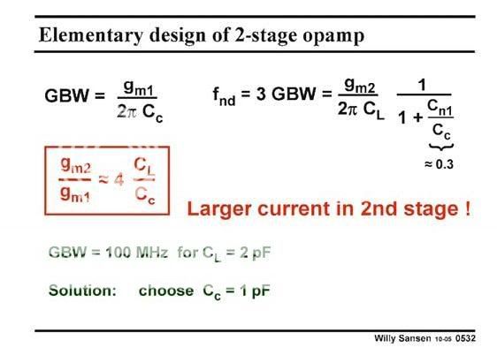
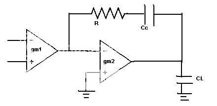
You are required to design two stages op amp as shown in the figure below. GBW of the op amp is 750MHz. Find the require range of R and calculated the phase margin. All assumption should observe no peaking (set 3xGBW) in the bode plot.

PM = arc tan ( f2 / GBW ) , CL = 2pF

Anyone can provide the working solution? Thanks!

design.jpg


Added after 43 minutes:

the formula, GBW = gm/2piCL where the gm is refer to gm1 or gm2 ?
 

2 stages op amp design

Hey!

Start analyzing it yourself first! It looks very easy, but don't ask directly for the homework solution, you're not going to learn that way man!
 

Re: 2 stages op amp design

Actually I got my analysis but not sure the answer because my theory not strong, that is why I hope you guy can provide the solution with explaination.

Solution 1
GBW = gm1/2piCc (is the formula correct?) or GBW = gm1/2piCL?
gm1 = 750M x 2pi x 1pF = 4.71m AV-1 if I set Cc = half of the CL

gm2 = 3 x gm1 = 0.014 AV-1 (why? anyone can explain to me?)

Range of the R,

Rmin = 1/gm2 = 70.8ohm , Rma x= 1/gm1 = 212.3ohm

Solution 2
3 x GBW = gm2/2piCL
gm2 = 3 x 750M x 2pi x 2pF = 0.028 AV-1

gm1 = gm2 / 3 = 9.42m AV-1 (why? anyone can explain to me?)

Rmin = 1/gm2 = 35.7ohm, Rmax = 1 / gm1 = 107.1ohm

so which method is correct?
 

Re: 2 stages op amp design

This is how i get the relation between GBW and 2nd pole, F2nd

GBW=gm1/(2pi*Cc)
F2nd=gm2/(2pi*CL)=3GBW=3*gm1/(2pi*Cc)
gm2/CL=3gm1/Cc
 

Re: 2 stages op amp design

yschuang said:
This is how i get the relation between GBW and 2nd pole, F2nd

GBW=gm1/(2pi*Cc)
F2nd=gm2/(2pi*CL)=3GBW=3*gm1/(2pi*Cc)
gm2/CL=3gm1/Cc

can explain regarding your formula?

Added after 1 minutes:

yschuang said:
This is how i get the relation between GBW and 2nd pole, F2nd

GBW=gm1/(2pi*Cc)
F2nd=gm2/(2pi*CL)=3GBW=3*gm1/(2pi*Cc)
gm2/CL=3gm1/Cc

can explain regarding your formula? like what is the purpose to set F2nd to 3GBW ? thanks
 

Re: 2 stages op amp design

Go ahead to check out a REAL 2-stage OPAMP design for your study:

**broken link removed**

You can get a sense of how to design an OPAMP from this free design.
 

Re: 2 stages op amp design

Hello, kingmaker

The formulas I got can be found in many textbooks. The way I get the 2nd pole is
short the input and output @ high frequency, or F2nd. The impedacne is 1/gm2 and the capacitance is around Cl+Cgs2. Then you can get F2nd=gm2/(2pi*Cl) if Cl is larger than Cgs2. For more details, you can go through slides named "Analog Design Essentials". Read Chapter 5. You can use free mirror to download that material.
 

Re: 2 stages op amp design

yschuang said:
Hello, kingmaker

The formulas I got can be found in many textbooks. The way I get the 2nd pole is
short the input and output @ high frequency, or F2nd. The impedacne is 1/gm2 and the capacitance is around Cl+Cgs2. Then you can get F2nd=gm2/(2pi*Cl) if Cl is larger than Cgs2. For more details, you can go through slides named "Analog Design Essentials". Read Chapter 5. You can use free mirror to download that material.

thanks for your replied. the link you given above is not exist anymore.
 

Re: 2 stages op amp design

The link still works. Try agian or just search for "analog deisgn essentials by sansen". Put key words "analog and design and essentials and sansen"
 

Re: 2 stages op amp design

yschuang said:
The link still works. Try agian or just search for "analog deisgn essentials by sansen". Put key words "analog and design and essentials and sansen"

thanks for your help! now I got it already. btw, I dont understand why Cc = half of the CL. Anyone can explain?

design1.jpg
 

Re: 2 stages op amp design

Hi,kingmaker

I think Cc=0.5Cl is an initial and reasonable assumption. It is ok to have Cc=0.3 or 0.4Cl. However, from the formula that gm2/gm1=4Cl/Cc, as you set Cc less than half Cl, you will burn more power. Let's assume Cc=0.5Cl, then gm2/gm1=8. If Cc=0.25Cl, then gm2/gm1=16, which means you will burn more power in the second stage. By the way, there is another assumption about Cc. In the slide, Cc is around 3.3 times Cn1, which is Cn1/Cc=0.3. So you can not set the value of Cc too small and there will be no miller effect I think.
 

Re: 2 stages op amp design

yschuang said:
Hi,kingmaker

I think Cc=0.5Cl is an initial and reasonable assumption. It is ok to have Cc=0.3 or 0.4Cl. However, from the formula that gm2/gm1=4Cl/Cc, as you set Cc less than half Cl, you will burn more power. Let's assume Cc=0.5Cl, then gm2/gm1=8. If Cc=0.25Cl, then gm2/gm1=16, which means you will burn more power in the second stage. By the way, there is another assumption about Cc. In the slide, Cc is around 3.3 times Cn1, which is Cn1/Cc=0.3. So you can not set the value of Cc too small and there will be no miller effect I think.

i see... got your point. thanks again.

1 question come to my mind. what is the relationship between dominant pole and GBW? And also, 2 stage op-amp same as miller cmos OTA?

by the way, do you any recommended book to read regarding the Feedback?
 

Re: 2 stages op amp design

kingmaker said:
yschuang said:
Hi,kingmaker

I think Cc=0.5Cl is an initial and reasonable assumption. It is ok to have Cc=0.3 or 0.4Cl. However, from the formula that gm2/gm1=4Cl/Cc, as you set Cc less than half Cl, you will burn more power. Let's assume Cc=0.5Cl, then gm2/gm1=8. If Cc=0.25Cl, then gm2/gm1=16, which means you will burn more power in the second stage. By the way, there is another assumption about Cc. In the slide, Cc is around 3.3 times Cn1, which is Cn1/Cc=0.3. So you can not set the value of Cc too small and there will be no miller effect I think.

i see... got your point. thanks again.

1 question come to my mind. what is the relationship between dominant pole and GBW(fT)? And also, 2 stage op-amp same as miller cmos OTA?

by the way, do you any recommended book to read regarding the Feedback?
 

Re: 2 stages op amp design

Hi, kingmaker

I think you do not have to go through all details about feedback and there is no one good book that covers all feedback theories. Sorry I can not help you about books on feedback. Analog Design Essentils is good because it tells you how to pick the value of Cc or gm2. You will see more details in chapter 6, which tells you a systematic way to design an opamp. The rest is how to simulate an opamp. You can take a look at the following link.
https://www.designers-guide.org/Forum/YaBB.pl?num=1155668476
 

Re: 2 stages op amp design

yschuang said:
Hi, kingmaker

I think you do not have to go through all details about feedback and there is no one good book that covers all feedback theories. Sorry I can not help you about books on feedback. Analog Design Essentils is good because it tells you how to pick the value of Cc or gm2. You will see more details in chapter 6, which tells you a systematic way to design an opamp. The rest is how to simulate an opamp. You can take a look at the following link.
https://www.designers-guide.org/Forum/YaBB.pl?num=1155668476

1 question come to my mind. what is the relationship between dominant pole and GBW? And also, 2 stage op-amp same as miller cmos OTA?
 

Status
Not open for further replies.

Similar threads

Part and Inventory Search

Welcome to EDABoard.com

Sponsor

Back
Top