rpg_dog
Newbie level 2
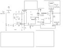
Hello all, I have pretty minimal experience in electrical engineering or design, everything I have learned has thus far been self taught over the internet. I have been developing a schematic for a device that uses 2 14500 li ion batteries which I would like to charge through a standard micro USB style connection, the batteries will be used through a PWM to heat up a nichrome coil to a desired temp. I am aware of the many considerations necessary when charging/discharging li ion batteries so I am trying to build in the protection circuit into the device for simplicity and saftey reasons. Keep in mind that this is the first time I have ever attempted anything like this and I am sure it is not complete, I would like some advice from someone who has a bit more knowledge than I in this area. I will attach my schematic in progress and ask my questions as clearly as i can. I plan to have this PCB printed professionally and would like to make sure it is correct before ordering.
1.) Well first off I guess I need to know if the charger IC I have chosen will work with 2 cells from a USB input 5v DC? The datasheet for the BQ2057W says it has an input voltage range of -.03v to +18v, but does that apply when batteries are wired in series (total 8.4v)?
2.) The Charger IC i have chosen allows me to compensate for different battery's internal impedences, must I have the actual battery in order to find the internal impedence, or is this info able to be calculated from the data sheet of the battery?
3.) I would like to integrate some sort of undervoltage shutdown to prevent excessive battery drain, will simply adding a zener diode between the battery and the load accomplish this?
4.) I took the diagram from TI's DV2057 and modified it to suit this circuit; is the Schottky diode at D1 necessary since I am using a PNP transistor rather than a pMosfet?
5.) I am realizing the importance of keeping the cells balanced so I am now thinking that I need an IC to auto balance when charging, I found the **broken link removed**, can this be used along with the BQ2057W I listed above?
6.) If I am correct in thinking that 5v DC in isn't enough to charge 2 4.2v cells in series, can wiring in some type of switch to change the battery configuration from series to parallel fix this? Will this also solve my cell balancing dilemma?
7.) Is the fuse at F1 necessary? The OKR datasheet insists, but if the OKR-T3-W12 can accept up to 14v DC, and my batteries can only reach 8.4v do I have to worry about shorting the chip? I want this PCB to be as small as possible, so I would like to remove unecessary components.
Thank you in advance for your time and any assistance anyone may have to offer.