Continue to Site

Welcome to EDAboard.com

Welcome to our site! EDAboard.com is an international Electronics Discussion Forum focused on EDA software, circuits, schematics, books, theory, papers, asic, pld, 8051, DSP, Network, RF, Analog Design, PCB, Service Manuals... and a whole lot more! To participate you need to register. Registration is free. Click here to register now.

1kW Flyback converter for battery charging

Status
Not open for further replies.
As I know, as the transformer primary inductance value increases, the flyback operates in continuous mode. In this mode the feedback control becomes difficult due to RHP zero,

but I want to know, will I have the problem in controlling the output current and voltage in CCM using PID control ?

When I reduce the transformer inductance, the flyback should be operating in DCM, in this the snubber value drastically increases, as the input current increases. Hence the wattage of RCD or resistor zener combination of snubber increases beyond 30 W.

Please suggest me implementable design.
 

My own personal preference would be for a diagonal half bridge for which no snubbing will be needed. The mosfets see no voltage stress beyond the dc input rail under any conditions. Any reflected energy from leakage inductance just recycles back to the source without drama.

I would also prefer DCM, even though peak current will be very high, its still manageable with a high enough dc input voltage.
Off line design is very different to designing something that is battery powered at much lower input voltage.

Current mode control will further reduce the compensation problems inherent in closing the feedback loop.

If the components for a single large flyback start to look unrealistic, interleaving two (or more) offers some definite advantages.

Interleaving two is dead easy, jut use both the outputs from an 0-50% push pull controller chip, each output driving its own separate flyback power stage
 
  • Like
Reactions: Ravi_H

    Ravi_H

    Points: 2
    Helpful Answer Positive Rating
Thanks Warpspeed , treez , BradtheRad for ur valuable replies.


Please tell me, how do I find out that my flyback transformer is saturating ..?
 

T
Please tell me, how do I find out that my flyback transformer is saturating ..?

When you fire it up for the first time, disconnect the feedback and manually control the duty cycle with a potentiometer.
Monitor the current on an oscilloscope and slowly increase both the incoming main dc voltage and the duty cycle.
You should see a nice straight current ramp in the primary which gradually gets larger as you increase both the volts and the microseconds.

The rate of current rise is determined by the inductance, and provided the inductance stays pretty constant, the ramp up should be a dead straight line.
When it reaches saturation, the rate of rise suddenly increases, and tends to spike up violently.

Infinite current is never a good thing !
But if you patiently adjust very carefully, and increase your ramp gradually, its pretty easy to see the peak current at which the straight line starts to bend upwards.

Then its just a case of adjusting the air gap to get the required inductance and saturation margin.
 
  • Like
Reactions: Ravi_H

    Ravi_H

    Points: 2
    Helpful Answer Positive Rating
also, if you take B(sat) as 0.3T, then I(sat) = B.A.N/L

where
L=inductance
A=core area
N=number of turns
 
  • Like
Reactions: Ravi_H

    Ravi_H

    Points: 2
    Helpful Answer Positive Rating
Thanx Warpspeed & treez for sharing ur knowledge with me.

Does the flyback transformer need to be reset ? The reset of the transformer should happen from the secondary, but does the reflected voltage on the primary require a path to dissipate or just by clamping it by using a zener will do ? what if RCD snubbers are not used in flyback, the voltage across drain-source does not damage the mosfet and without removing the ringing. What issues may occur ?

If the flyback step down converter is operated in continuous mode, is there more chance of the transformer not getting reset over time ?

Please guide me on the implementation issues of flyback.
 

When the mosfet(s) turn off, the flux in the core collapses producing equal volts per turn flyback in all windings.
The voltage rises very fast until a diode "somewhere" clamps this rising voltage into a load. Hopefully there are enough turns on the secondary to cause the output rectifier to conduct and feed most if not a ll of the stored energy into the load on the output.

If the load suddenly disappears, as can happen, the voltage rises a bit further until the two diodes in the primary conduct, feeding all of the surplus energy back to the source almost without loss.

It's a wonderful system, because the mosfet drains are voltage clamped to the dc supply rails, and no overvoltage spiking can occur under any conditions.

You do not need any snubbers or zeners, the clamping diodes take care of everything, and there is no net loss of power, or anything to get wastefully hot.

In discontinuous mode full core reset will occur each cycle, but continuous mode the core is only partially reset, which is the normal condition for CCM.
 
  • Like
Reactions: Ravi_H

    Ravi_H

    Points: 2
    Helpful Answer Positive Rating
Thanks Warpspeed.

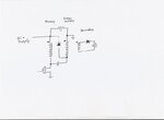
Flyback.JPG

Please find the attached image of the flyback design I wish to make.

The problems I'm facing, I wanted to solve is related to this design.

Please provide help in this circuit.
 

Only way I can see would be to fit a third energy recovery winding.

energy recovery.jpeg

Primary and energy recovery winding must be bifilar wound and exactly equal in turns. Secondary can have any turns.

Ac voltages across the two windings will be identical, especially as both ends are connected together with capacitors.

Primary is connected to dc input voltage, energy recovery winding is grounded.

When mosfet turns off exactly equal flyback voltages will appear across both primary and energy recovery winding. If the flyback voltage exceeds the dc supply voltage the diode conducts and any excessive voltage spike will be clamped.

The mosfet drain will be therefore clamped to exactly twice the dc supply voltage.

Any rogue leakage inductance will also exist in the energy recovery winding, but the capacitor to the drain effectively clamps any spike.

The only disadvantage is that it clamps the drain to twice the dc supply voltage, whereas the diagonal half bride circuit clamps to the supply voltage.
Therefore requiring mosfets of twice the voltage rating.

It does work, and its very efficient at high power, but its less suitable if you have very high input voltages.
 
  • Like
Reactions: Ravi_H

    Ravi_H

    Points: 2
    Helpful Answer Positive Rating
4 x 250W interleaved fly-backs better than 1 x 1kW unless you have some pretty nice large planar cores to minimise leakage...
 
  • Like
Reactions: Ravi_H

    Ravi_H

    Points: 2
    Helpful Answer Positive Rating
Ty Warpspeed and Easy peasy.

Yes I know that by the design given in post #48, the mosfet is selected having voltage much greater than twice the input voltage.

But if the input inductance of the primary is kept low, the converter operates in Discontinuous mode, where the current increases, causing greater wattage loss across the zener clamping connected n parallel with the primary of the transformer.

If the converter is operated in continuous mode, I'm getting the required output by having duty cycle greater than 50%, in such case the current decreases and the wattage required by zener reduces.

The zener voltage is choosen twice the input voltage, then also the drain to source voltage has ringing and a shoot much greater than twice the input voltage. How to reduce that shoot in voltage across drain to source. ?

If the duty cycle is greater than 50 % that too in continuous operation, will the transformer misbehave as the reset time is reduced ? will the transformer pile up current in the primary side and saturate over time ?

To reduce the wattage across the zener acting as a clamping snubber, I wish to operate flyback in continuous mode.

Please guide me.
 

Voltage overshoots are caused by too much leakage inductance, pri to sec, running continuous mode will require big snubbers on your o/p diode, and create the lot of RFI, with initial current spiking on your fet, even if the max turn off current is lower.

However the energy transferred is now 0.5 Lpri(I2^2 - I1^2) .freq, in watts, so a larger Lpri means a slower change to a higher power operating point, and more difficult control in CCM, due to the right hand plane zero.

Not really recommended for 1kW, unless you have large planar cores with low leakage...
 

Have to agree with Easy P.
Continuous conduction mode may appear to help with this problem, but create some even greater future hurdles when it eventually comes to taming the the control loop.

Especially for battery charging, you cannot always guarantee having a minimum load sufficient to keep it in continuous conduction mode.
It will need to work in both, which becomes more complicated than designing for discontinuous mode right throughout the whole range up to full maximum output.
 

Are we saying that if a current mode CCM flyback was light-loaded to the extent that it went into DCM, then if it had been stable in CCM at heavier load, we are saying that there is a chance of it going unstable in DCM when lighter loaded?
As you know, all CCM hard switched converters eventually go into DCM if light loaded enough.
 
  • Like
Reactions: Ravi_H

    Ravi_H

    Points: 2
    Helpful Answer Positive Rating
It depends on the application.
If its in (say) a TV set, it will always run with the same pretty constant full load and never see anything less than that.

But some applications may need to run fully unloaded sometimes, and a battery charger can come pretty close to that condition.
 
  • Like
Reactions: Ravi_H

    Ravi_H

    Points: 2
    Helpful Answer Positive Rating
I believe that if any hard switched, current mode converter which is in ccm at full load, is stable at full load, and stable at all loads where it is in CCM, then it will definitely be stable at any lighter load where it is in DCM.
 
  • Like
Reactions: Ravi_H

    Ravi_H

    Points: 2
    Helpful Answer Positive Rating
Stability is only one issue.
You can reduce the low frequency loop gain, and increase the integral time constant, and make it as stable as a rock.

But it may not regulate too well, and have pretty sluggish response to load changes.
 
  • Like
Reactions: Ravi_H

    Ravi_H

    Points: 2
    Helpful Answer Positive Rating
Thanx Easy peasy, Warpspeed , treez for ur valuable response.

As I understand once a system (say flyback converter) is modeled to find the output to input ratio using Laplace transform, the system poles and zeros are obtained.

1) Then how come the system transfer function changes with its operation in continuous or discontinuous.

Whatever poles and zeros obtained by system modeling should remain the same irrespective of its operation, I feel.

2) The system stability as I understand is defined by the poles and not zeros. So why are the mention of zeros in the case of flyback ?
 

Discontinuous operation pumps "packets" of energy per cycle.
So many millijoules per cycle of stored energy, depending on duty cycle, and where you terminate the inductor ramping up cycle.
The output on the secondary is a high impedance. As you load down the output, the voltage falls because its a constant power system in terms of duty cycle.

Continuous mode is an entirely different system. It becomes rather like a normal transformer, where the output voltage is determined by duty cycle, and the turns ratio. As you load it up, duty cycle hardly changes, but the peak currents do increase with load because of all the stored non released energy.
The ramp sits on top of a constant dc.
The output impedance on the secondary becomes a low impedance, and it will transmit much greater power at higher load with very little change in duty cycle.

This creates a very sudden and dramatic change in the required loop gain to achieve good regulation and stability.
And the requirements change with both output voltage control, and output current limit control.

Its not "just" the loop phase shift versus frequency, but the gain requirement changes too.

Think about current limit operation.

In DCM the output impedance is high, and it will easily tolerate high gain, and stability will not be a problem.
In CCM mode you have a very low impedance source feeding a low impedance battery. Even a very small change in duty cycle will have a dramatic effect on output current, and that requires a lot less gain to achieve stability at low frequency.

But you cannot have both !

Similar problem with voltage control, the whole thing changes, and it can be pretty difficult to strike a compromise, especially as a battery charger requires a very high tolerance to load changes from absolutely flat out in current limit, right down to almost no load at all in constant voltage mode.
 

The system stability as I understand is defined by the poles and not zeros. So why are the mention of zeros in the case of flyback ?
the zeros of the power stage transfer function of a flyback are involved and are a feedback loop parameter...for a flyback in ccm or dcm, there is a zero due to the esr of the output ccap, and for ccm there is the dreaded R.H.P.Z. -so poles and zeros are considered in stability of ccm and dcm flyback
 

Status
Not open for further replies.

Part and Inventory Search

Welcome to EDABoard.com

Sponsor

Back
Top