Welcome to our site! EDAboard.com is an international Electronics Discussion Forum focused on EDA software, circuits, schematics, books, theory, papers, asic, pld, 8051, DSP, Network, RF, Analog Design, PCB, Service Manuals... and a whole lot more! To participate you need to register. Registration is free. Click here to register now.
Hi Peggy,
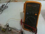
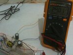
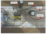
Sorry i was busy and your two multimeter puzzle become brain teaser to me, finally I found that in output -2 one end of winding is connected to diode and other end(i.e black wire) you forgot to ground. in such case output-2 become open circuit. output-1 is good one end is grounded and feedback is taken from it. output-2 is open circuit scine you are not grounded black wire, when you measure with multimeter, multimeter internal resistor closes the circuit and shows the voltage of DC pulse train scince no filter across output-2 (output capacitor you are used is not in circuit with respect to S2).
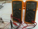
when two multimeters come into picture this Ac component in S2 couples to S1 and influence feedback, resulting in voltage variation.
Scince Aux winding of your transformer carry max 200ma of current you can expect only 50mA per single output and 100mA combined. carry out load test on your power supply.
This site uses cookies to help personalise content, tailor your experience and to keep you logged in if you register.
By continuing to use this site, you are consenting to our use of cookies.