Continue to Site

Welcome to EDAboard.com

Welcome to our site! EDAboard.com is an international Electronics Discussion Forum focused on EDA software, circuits, schematics, books, theory, papers, asic, pld, 8051, DSP, Network, RF, Analog Design, PCB, Service Manuals... and a whole lot more! To participate you need to register. Registration is free. Click here to register now.

12v Motor Timer Circuit Problem

Status
Not open for further replies.

ryanturner

Newbie level 4
Joined
Feb 4, 2012
Messages
6
Helped
0
Reputation
0
Reaction score
0
Trophy points
1,281
Activity points
1,333
Hi guys,
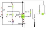
I have this circuit connected to a battery producing 12.6V, the circuit works perfectly and does what i need it to when connected to a test 10v motor. The Voltage I get across the motor is 11V.
The actual motor i am using is rated at 12V so i thought 11 would just make it run slower but does not make it run at all.
Here is the circuit, any ideas what i can do to modify it to get a higher voltage drop across it? Use an Op Amp maybe?
Thanks in advance!
Kayak Circuit.jpg
 

Strange circuit - two of the transistors are permanently off (fortunately!), one is connected as a switch and one as an emitter-follower. It looks like an H-bridge but isn't since all the transistors are npn. You could replace them all with just one switching transistor and that would give you closer to 12V across the motor.

As to why it's not working with a 12V motor if it does with a 10V motor: Are you sure the 12V motor is a simple brushed DC motor? Because you are right that (if it is the right type of motor) then it would just run a little slower. It's not a very big motor trying to draw more current that the battery and transistors can provide is it? Compared to testing with a much smaller 10v motor?
 
Last edited:

Hi dear ryanturner *
your circuit have a few problem !
two transistor don't have grand (up)...
so these will be turn on but in their emitter there are a load so those worked on linear region.
you must take two pnp transistor and replace them with down transistors...
 

yeah two transistors do not function atm. idea was that once the circuit was running ok, ill connect the other two straight from the battery for a reverse motor function. (the thing im using for is to pump water into a live bait well and the reverse function would let me drain it.
The transistors can take 3A which is why i used them, incase the motor needed to draw alot. The 10v motor is a little smaller but not much. Ill have to have a look at the 12v when i get a chance.

You saying using just a single transistor would work then?
 

For the current function, yes, a single transistor as a switch would work perfectly. Sorry for the quick hack-up of your diagram, but you can see what I mean below. It's a standard transistor switch circuit for switching relays, motors, whatever:

motor.jpg

I guess you found your circuit because of the reverse function that you want - it looks like what is called an H-bridge circuit, but it is wrong. An H bridge needs pnp transistors for the top two, not npn. Your circuit, if you tried to use it as an H-bridge, would short out the battery!

Anyway, it sounds like you don't need the H-bridge, if you can manually do something for the occasions when you want to pump backwards. Here is an easy way to do that:

Simply use a DPDT (double-pole, double-throw) toggle switch connected as below:

motor2.jpg

The first shows the physical wiring, the second is a schematic showing how it works. Just connect the Vs and 0V from this in place of your motor connection in the top diagram, between transistor and power. When the toggle switch is operated, it just reverses the supply to the motor. It's a very useful little trick. Saves you messing about with the battery. Use a standard 10 amp toggle switch. You should only operate the switch while the motor is stationary though, otherwise you might get a lot of current being drawn as the motor is hard-reversed.
 

Status
Not open for further replies.

Part and Inventory Search

Welcome to EDABoard.com

Sponsor

Back
Top