Continue to Site

Welcome to EDAboard.com

Welcome to our site! EDAboard.com is an international Electronics Discussion Forum focused on EDA software, circuits, schematics, books, theory, papers, asic, pld, 8051, DSP, Network, RF, Analog Design, PCB, Service Manuals... and a whole lot more! To participate you need to register. Registration is free. Click here to register now.

10V-28V to 5V@1A regulator

Status
Not open for further replies.

eriksen

Junior Member level 1
Joined
May 13, 2014
Messages
19
Helped
1
Reputation
2
Reaction score
1
Trophy points
3
Visit site
Activity points
171
Hi,

As the title says I am designing a regulator to be able to supply 5V for use with microcontrollers in cars and trucks.

I have started designing a regulator based on LM25011 from TI. I am quite experienced with microcontrollers but have never designed/made a power supply.

What I am wondering is if my solution here will work, and how steady it will be able to keep the 5V and how much overshoot to expect, when connecting a fully charged 24V battery(Approx 28V+), and a low 12V battery(Approx 10V).

Anyone got experience with anything similar?


Attached is a picture of the schematic. Hoping for some pinpoints in the right direction.

Thanks.


-Fredrik
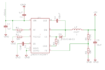
12-24Vreg.PNG
 

Hi,

moder switch mode ICs are pretty good.
Especially with the soft start function you can avoid overshot at power on.
Line regulation and load regulation is also good.

Try it and see it.
Adding capacitor at the output may help.
Also a small capacitor across R5 could optimize regulation.
Take care with the layout.

Check if you really want the PGD resistor to GND.

Hope that helps
Klaus
 
Thank you very much for your prompt response.

About the PGD pin the datasheet says:
"Logic output indicates when the voltage at the FB pin has increased to above
95% of the internal reference voltage. Hysteresis is provided. An external
pull-up resistor to a voltage less than 7V is required."

I connected it to GND because it is less than 7V!
But maybe I should leave it unconnected since I don't have another reference voltage?
 

Hi,

if i understand the datasheet right, then PGD is an opendrain output. So with no pullup there will be no signal at the output.

But it´s ok if you don´t need it.

Klaus
 

you want to make regulated 5V power supply.i don't know why you are creating trouble for your own work.why you do not use 7805.It can provide 1A.
 

you want to make regulated 5V power supply.i don't know why you are creating trouble for your own work.why you do not use 7805.It can provide 1A.
Thanks for your answer.

Mainly I thought because of low power waste and low heat.
The 7805 would need a heat sink for dropping from 28V to 5V @1A wouldn't it?

Hi,

if i understand the datasheet right, then PGD is an opendrain output. So with no pullup there will be no signal at the output.

But it´s ok if you don´t need it.

Klaus

Thanks four your answer.

Do you mean by this that I should leave it floating?


-Fredrik
 

you want to make regulated 5V power supply.i don't know why you are creating trouble for your own work.why you do not use 7805.It can provide 1A.

Hi,
He shouldn't use 7805 at all! If you he uses 7805 with 28V input voltage (assuming that 28V input is acceptable for 7805) , it will dissipate 23W at 1A output current. It will need a very large heat-sink or it will shutdown itself.

@OP: as KlausST stated , PGD Pin is open drain. you should a pull-up resistor and connect the pull-up resistor to the microcontroller power supply (5V).

as for 5V -1A supply , you can also use LM2576 , it has better footprint for connecting it to any heat-sink and also has a 5V model, so your external components will be minimum (only 4 components).

Thanks, memarian.

I have the regulator mentioned in this thread as the main current provider for the circuit. It accepts 12-24V and regulates it down to 5V which is used by some other components and then fed into the next regulator which regulates 5V down to 3V for the microcontroller.

I interpret what you are saying about the PGD as connecting a 10k resistor to the output of my regulator(input of the next regulator). Is this correct?

Thanks for the suggestion of LM2576, I will look into it.

-Fredrik

Hi,

you should connect a 10k resistor between PGD Pin and microcontroller Power Supply and connect PGD Pin to one your microcontroller pins.

For example , if your microcontroller Power Supply is 3V, The 10K resistor should be connected between PGD Pin and 3V, then PGD Pin to Microcontroller (check the attached picture).

Pin.png
 
Hi,

you should connect a 10k resistor between PGD Pin and microcontroller Power Supply and connect PGD Pin to one your microcontroller pins.

For example , if your microcontroller Power Supply is 3V, The 10K resistor should be connected between PGD Pin and 3V, then PGD Pin to Microcontroller (check the attached picture).

View attachment 105311

Thanks again for a thorough answer. Now I understand what you are saying. The problem is that I cannot access the 3V from this PCB as the microcontroller is placed on a second stacked PCB.
Will the regulator work if the PGD is left floated?

Thanks.
-Fredrik
 

Thanks again for a thorough answer. Now I understand what you are saying. The problem is that I cannot access the 3V from this PCB as the microcontroller is placed on a second stacked PCB.
Will the regulator work if the PGD is left floated?

Thanks.
-Fredrik
Hi,

Yes! it's open drain and only a monitoring Pin. You can leave it float and there is no problem at all.
 
Hi,

PGD: there is no problem when this pin is left floating. It will not oscillate and it will not drow crowbar currents as it is with floating inputs.

Only if you want to use this pin thenn feed it to the ucontroller board and place the pullup there.

The regulator will work either way. Don´t worry.

Klaus.
 
Status
Not open for further replies.

Similar threads

Part and Inventory Search

Welcome to EDABoard.com

Sponsor

Back
Top