Continue to Site

Welcome to EDAboard.com

Welcome to our site! EDAboard.com is an international Electronics Discussion Forum focused on EDA software, circuits, schematics, books, theory, papers, asic, pld, 8051, DSP, Network, RF, Analog Design, PCB, Service Manuals... and a whole lot more! To participate you need to register. Registration is free. Click here to register now.

10kV Power Supply Problem

Status
Not open for further replies.

cm_newbie

Newbie level 4
Newbie level 4
Joined
Mar 18, 2014
Messages
5
Helped
0
Reputation
0
Reaction score
0
Trophy points
1
Visit site
Activity points
46
Hi,

I am new to hardware design. I had made some simple devices but I have now been asked to make 10kV power supply. It is supposed to be a high voltage, low current device 10kV and 3mA maximum. I am trying to adapt 5kV power supply I have got available. The 5kV uses two ferrite transformers to step up the voltage from 20V to around 2.5kV each. I tried to increase voltage on primary coil to 40V but it only gives ca. 4kV (i.e. 8kV total). So I decided to connect 4 ferrite transformers in series and power them from 20V on primary coil each. And after adjusting circuit on the secondary coils of ferrites I get... ca. 8kV maximum again... So my question is why does the second method not work? Is there anything I could adjust to achieve or would it be best to get new ferrites with more turns and just use two transformers?

Thanks
 

to see what happen, pls provide more detail such your schematic, your wire connection ...etc
 

to see what happen, pls provide more detail such your schematic, your wire connection ...etc

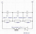
Ok, I have just taken one of the ferrite transformers apart and now this question changes into query about ferrites. It turns out it has 10 turns on primary coil and 160 on secondary coil. So if I connect 20V to the primary coil it will step it up to 320V. Then there is a bank of three series capacitors (20nF 1000V) connected to the secondary coil of the ferrite. When switched on voltage measured on the output is about 3.2kV. Does that mean that if change the capacitors on the secondary coil to let's say (20nF 2000V) it will be able to hold higher voltage?
 

are the ouput coil connect to cap directly without any diode? if yes, it just like a LC tune circuit. ouput step up by LC resonate. output is ac.

In series of transformer ouput will cause output inductance changes, you have to adjust the cap such that LC resonate freq same the apply freq.

also all winding of primary for all transformers should parellel connect to ensure output voltage balance

Yes there is BY8412 rectifying diode connected to the secondary coil. I attached the circuit connected to secondary coil here: SecCoil.jpg

It works fine when 20V 30kHz signal is connected to primary coil. Then between + and - on the output you can measure about 2.5kV. But I need to increase that to 5kV. I was hoping I could do it by just increasing input voltage but it only went to 4kV maximum. (8 if two connected in series).

Then I decided to connect 4 circuits as attached above in series to get 10kV in total. But it did not work either so I am a bit lost really...
 
Last edited:

what instrument you used to measure the voltage?
what is its internal resistance ?
when the 4 circuit connected in series, have u measure the voltage of each circuit? are they have same reading?
 

BY4182 circuit is a simple rectifier circuit, with three capacitors sharing the output voltage, the resistors make sure they do! Have you searched for COCKCROFT WALTON voltage multiplier on wikipedia? Its a way of multiplying AC voltages and rectifying them at the same time - leaves the oscillator alone :)
Frank
 

I thought you are driving primary as flyback converter. Vin*D/(1-D)=Vout.
With 10:160 turns ratio and 50% duty, you can get output 16 times of input only.
The reason why you get 2.5KVDC because you get the HV by leakage inductance of transformer, only a very small load at output will cause voltage drop quickly.
When you connect the 4 circuit in series, the output HV will discharge air causing energy loss which act as a loading. when you use instrument measuring the HV also add loading to output, that why output can’t get the exact voltage 4* 2.5KV.
 

the current in the primary side changes abruptly due to the diode in the secondary (it supplies very small current to the resistors for half cycle and zero current in the next half that is an abrupt change in current) and that abrupt change in current in the primary will induce high voltage (due to high rate of change of current with respect to time) in the primary and multiplied by the turns ratio will give the high voltage at the secondary
 

I thought you are driving primary as flyback converter. Vin*D/(1-D)=Vout.
With 10:160 turns ratio and 50% duty, you can get output 16 times of input only.
The reason why you get 2.5KVDC because you get the HV by leakage inductance of transformer, only a very small load at output will cause voltage drop quickly.
When you connect the 4 circuit in series, the output HV will discharge air causing energy loss which act as a loading. when you use instrument measuring the HV also add loading to output, that why output can’t get the exact voltage 4* 2.5KV.

Ok, would it help if I increased the ratio of the ferrites (from 1:16 to 1:32) and connect just 2 in series ?
 

BY4182 circuit is a simple rectifier circuit, with three capacitors sharing the output voltage, the resistors make sure they do! Have you searched for COCKCROFT WALTON voltage multiplier on wikipedia? Its a way of multiplying AC voltages and rectifying them at the same time - leaves the oscillator alone :)
Frank

I suppose I couldn't use COCKCROFT WALTON voltage multiplier in my circuit on the secondary coil side. If I added another set of capacitors and a diode it would mess with the LC resonance circuit wouldn't it?
 

No it has nothing to do with resonance, the only voltage multiplier that uses resonance is tesla coil

- - - Updated - - -

Doubling the turns ratio will allow you to use only two series multipliers
 

An auto ignition coil can generate that with a suitable diode cap rectifier bridge using a sine wave source
Voltage Gain is around 1k, but if you don't provide some cooling, the secondary windings can get too hot and fuse open from excessive corona.

Or attach silicon wires to the Flyback HV generator from an old TV or CRT monitor and get 40kV or tune it down to 10kV.
 

Status
Not open for further replies.

Similar threads

Part and Inventory Search

Welcome to EDABoard.com

Sponsor

Back
Top