Continue to Site

Welcome to EDAboard.com

Welcome to our site! EDAboard.com is an international Electronics Discussion Forum focused on EDA software, circuits, schematics, books, theory, papers, asic, pld, 8051, DSP, Network, RF, Analog Design, PCB, Service Manuals... and a whole lot more! To participate you need to register. Registration is free. Click here to register now.

1000 watt pure sine wave inverter

Status
Not open for further replies.
Thank you very much for the responce.
I will try to find the inductors u suggested
Pls explain to me how i can make the inductors as you said, i realy want to try this inverter first before i try another more complex one.
I also want to find out from you if you pls have an simple inverter circuit diagram that does not involve the use of inductors.
Thank you very much for all the help you are giving me in this build i am trying. thank you sooo much
Have a plesent day
Enjoy
 

To make inductors at home, you would be needed a thick enameled copper wire, a iron core element & an inductance meter.


This inverter can still work without an inductor, but that would be a square wave. You can try with inductor value less than 1H if it is hard to find. your inverter will still work.

Every inverter needs an inductor, maybe in smaller value if it is a pure sine wave generator. Inverter helps to smooth the waveform.

- - - Updated - - -

Here is a very simple modified sine wave inverter. It will also require an inductor, but small as 250mH.
http://www.m0ukd.com/electronics/modified_sine_wave_inverter/
 

In a sine wave inverter, the inductor, along with capacitor, is used for filtering the output into a pure sine wave. If the sinusoidal PWM frequency is high, the inductance required is small.

For modified sine wave inverter, no inductor is required at the output. And certainly not one with a value as large as 250mH.
 

like i told genovator previously if you realy need pure sine wave you need to program your micro controller for that to using discreet component wont be that easy for you.
 

Thanks for telling me. I know it is not a good option. That is why I told reynier many times that this circuit is not good to use, but easy to make. I am already working on modified sine wave inverter. My program is almost done.


Thanks.
 
Hi Genovator and Kabiru
I would like to build a proper inverter, and i realize that one with a micro controller is the best way to go
but i dont know how and is not able to program one.
pls can u advise on how to program one and what i need to program one.
Thank you very much
Hope to hear from u soon
 

Hello reynier1223, you need to get programer so that you will have something to burn your pic,secondly you will need to write your code to generate your pwm signals.
 

Since you are new to these things, specially with microcontrollers, it would be nice if you make an inverter which is already made and tested by someone. Search in google for such inverter projects and we will find some also....
 

Thankyou for the advice;
I have found a place that i can get a pic programer kit, so i will have one to program the micro controller with.
All i need now is the program that i need to burn the micro controller with.
Genovator, u said that u are busy with a program, will you mind sending it to me when u are done with it, and the circuit diagram that you are writing it for.
Thankyou in advance
Enjoy you day
 

I will be happy to help you. But I cant advise you to use my program. I am not a programmer, just have some knowledge in it. And I have never tested my design before. It works in proteus but it may not work in real life. So it will be risky to use my program. If it fails, your time & money will be wasted. As I said, any circuit & program which was tested by someone before would be a good option to choose.

It don't know how much time it would take to complete. When I am done, I will post it for everyone's views and comment.
 

Hello reynier 1223, i think you should start with simple square wave first before moving to the next level
 

Good day Kabiru
I can not, for i live in south africa, and here we only use sin wave. so if i build a square wave inverter i would not be able to use it at all
 

Sine wave is used in every country, in India too. But I have a square wave inverter which runs my whole house appliances. Only some computer UPS, AC motors and a very few other components cannot be run with square wave. So if you have such components, you are left with no option than sine wave. some links:

https://www.wpi.edu/Pubs/E-project/Available/E-project-042507-092653/unrestricted/MQP_D_1_2.pdf
https://www.wpi.edu/Pubs/E-project/...-190851/unrestricted/PWM_Techniques_final.pdf


Genovator
 

Hello genovator, the inverters shown in the link you posted they are modified sine wave not pure sine wave and the first one has no voltage regulation.
 

Hello genovator, the inverters shown in the link you posted they are modified sine wave not pure sine wave and the first one has no voltage regulation.

The 2nd link is for a pure sine wave inverter. Sine wave generation is achieved using a Bubba oscillator. Details are given in the document.

- - - Updated - - -

Good day Kabiru
I can not, for i live in south africa, and here we only use sin wave. so if i build a square wave inverter i would not be able to use it at all

I think Kabiru meant that, instead of heading straight into the design of a sine wave inverter, design a square wave inverter for educational purposes. You can learn a lot from it, as well as gain valuable experience. Then, you should go on to designing a sine wave inverter.
 

I gave those links just for reference before reynier starts to build one. :smile: The first one is just a simplest form. It still requires charger, start/stop button and lots of other things.
 

Good day Genovator
Thank you for the post of the links, I think that i am going to try building the first link, for my first try.
I surrpose there is a way to intergrate a voltage regulation circuit into that circuit diagram, pls can u advise on this, as i would realy like to be able to use it in my prodject
Thank you very much
Enjoy
 

You can simply download the hex file and simulate it before building it
 

Good day Kabiru
What do u mean with download the hex file and simulate it?
And with what program would i simulate it.
I just want to incorporate a voltage regulation circuit into the diagram that Genovator gave
Enjoy you day
Thanks
 

There are some simulation software available in the market like Proteus. You have to design the circuit as shown and simulate it with the hex given. There is no option left to add a voltage regulator in the **broken link removed**. Voltage can be regulated by pwm and there is no source code to add this feature. May be this is the reason a 10v to 240v transformer is used. With no regulation there should be a ferroresonant transformer.

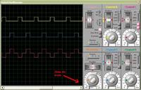
In the mean time I also simulated the hex. I found it is producing 12.5Hz instead of 50Hz. I could be wrong.
 

Status
Not open for further replies.

Part and Inventory Search

Welcome to EDABoard.com

Sponsor

Back
Top