Continue to Site
Follow along with the video below to see how to install our site as a web app on your home screen.
Note: This feature may not be available in some browsers.


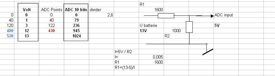
Can we configure 10 bit ADC in 16f676 as 8 bit? If yes then how to do it?


Convert this value to 255 range using
myadcval = 1023 / 4.011764705882353;
myadcval will be in the range 0 to 255..


One more thing i wud like to know. i am using mikroc pro for PIC and 16f676. But when i declare array of 20 its giving an error 'Not enough RAM?FLOC_Main'. What to do if I want to use larger array?
put const keywordOne more thing i wud like to know. i am using mikroc pro for PIC and 16f676. But when i declare array of 20 its giving an error 'Not enough RAM?FLOC_Main'. What to do if I want to use larger array?
//#fuses INTRC_IO, NOWDT, NOPROTECT, BROWNOUT, PUT

#define ON 0
#define OFF 1
#define timer_val 0
#define BATTERY_CHARGE PORTC.B5
#define LOAD PORTC.B4

unsigned int Panel_Value, Battery_Value,FLAG_1,FLAG_2=0,FLAG_3,FLAG_4,FLAG_5,FLAG_6,FLAG_7,FLAG_8;

//int OnPulse = 217;
//int OffPulse = 38;
//char TOG = 0;
unsigned int i = 305,j=1, factor = 0,divide_val=0,k=14,l=3;

void convert(int m,int n){
 divide_val = ((Battery_Value/4) + k);
 if(divide_val>=200){
 divide_val = divide_val + l;
 l=l+3;
 if(l==42){
 l = 3;
 }
 }
 if(TMR0 >= divide_val){
 LOAD = OFF;
 //k++;
 //FLAG_1=0;
 }
 if(k>=134){
 k=14;
 FLAG_1 = 0;
 }

}


void interrupt(){
     if(INTCON.T0IF){
     T0IF_bit = 0;
     TMR0 = timer_val;
     }
     if(FLAG_1 == 1){
     LOAD = ON;
     //FLAG_2 = 1;
     }

}

void main() {

     TRISA = 0xff;      //port A as input
     TRISC = 0x00;      //port C as output
     PORTC = 0X00;      //INITIAL VALUE ON PORTC

     ADCON0 = 0b00000000;         //Left Justified
     ADCON1 = 0b00110000;         //Clock derived from internal RC oscilator
     ANSEL  = 0b00000011;         //channel AN0 and AN1 as analog input

     INTCON = 0b10100000;
     INTCON.T0IF = 0;
     //CMCON0 = 0x07;               //Disable the comparators
     T0CS_bit = 0;
     PSA_bit = 0;  //Prescaler is assigned to Timer0 module
     PS0_bit = 0;  //TMR0 rate 1:1
     PS1_bit = 0;
     PS2_bit = 0;

     //TMR0 = timer_val;

                      while(1){
                                   Panel_Value = ADC_Read(0);
                                  Battery_Value = ADC_Read(1);

                                  if(Panel_value>=122){       //AD Value for 3 volt
                                  ///FLAG_1 = 1;
                                  BATTERY_CHARGE = ON;
                                          if(Battery_Value>=430){  //AD Value for 12v
                                          //FLAG_2 = 1;
                                          BATTERY_CHARGE = OFF;
                                          }
                                  }

                                  if(Battery_Value > 430){
                                  BATTERY_CHARGE = OFF;
                                  }

                                  if(Panel_Value <= 30 ){   //Panel AD value for 1v <=40
                                  //FLAG_3=1;
                                  BATTERY_CHARGE = OFF;
                                  LOAD = ON;
                                              //if(Panel_Value >=40 && Battery_Value <= 321){  //Panel voltage 3v and battery voltage 9v
                                              //FLAG_4=1;
                                              //BATTERY_CHARGE = ON;
                                              //LOAD = OFF;
                                              //}
                                  }

                                  if(Panel_Value > 321){    //Panel Voltage 9 v
                                  //FLAG_6=1;
                                  LOAD = OFF;
                                  }

                                  /*if(Battery_Value <=425 && Battery_Value > 321){              //Battery voltage between 12v & 9v
                                  FLAG_1=1;
                                  FLAG_2=1;
                                           factor = Battery_Value - i;
                                           if(factor >= 200){
                                                     factor = factor + j;
                                                     j++;
                                                     if(j == 25){
                                                          j = 1;
                                                          }
                                                     }
                                           if(TMR0>=factor){
                                               LOAD = OFF;
                                               //i=0;
                                               //TMR0=0;
                                               //FLAG_1 = 0;
                                               i = i-2;
                                               if(i==97){
                                               i=305;
                                               }
                                            }
                                            //if(Battery_Value !=(Battery_Value<=425 && Battery_Value>321)){
                                            //FLAG_1 = 0;
                                            //}

                                  }*/
                                  if(Battery_Value <=425 && Battery_Value > 310){
                                  FLAG_1 = 1;
                                  FLAG_2 = 1;
                                  //k++;
                                  if(Battery_Value==425){
                                  convert(425,14);
                                  }

                                }

                                 /*if(FLAG_2==1){
                                     FLAG_1=0;
                                     FLAG_2=0;
                                    }*/

                                    //if(Battery_Value !=(Battery_Value<=425 && Battery_Value>321)){
                                           // FLAG_1 = 0;
                                            //}

                                   if(Battery_Value <= 310 ){        //Battery ADC value for 9v 310,309
                                     //FLAG_7 = 1;
                                     while(Battery_Value<=400){
                                     Battery_Value = ADC_Read(1);
                                     LOAD = OFF;
                                     }
                                     LOAD = ON;
                                  }

                                  /*if(Battery_Value<310){
                                  LOAD = OFF;
                                  }

                                  if(Battery_Value> 440){
                                  LOAD = ON ;
                                  }*/

                              }

}