Continue to Site

Welcome to EDAboard.com

Welcome to our site! EDAboard.com is an international Electronics Discussion Forum focused on EDA software, circuits, schematics, books, theory, papers, asic, pld, 8051, DSP, Network, RF, Analog Design, PCB, Service Manuals... and a whole lot more! To participate you need to register. Registration is free. Click here to register now.

1 KHz Sine Wave Oscillator with 20V p-p output

Status
Not open for further replies.

luben111

Advanced Member level 1
Joined
Mar 2, 2002
Messages
489
Helped
111
Reputation
223
Reaction score
107
Trophy points
1,323
Location
UK
Visit site
Activity points
3,927
Hi,

I have to build a sine wave generator on 1 KHz and output voltage 20V p-p. The power supply is ~20-24V (step up from 3V battery) . The load is negligible - less than 1uA. The design should be cost efficient and to consume less than 60uA.

Distortions of the sine wave up to 5-10% are accepted but they have not to contain high frequency spikes or glitches (the curve should look "smooth").

If it's possible to control the step up regulator to directly generate the sine wave it will be even better.

Any ideas and comments will be appreciated.

Thank you.

Best regards,
Luben
 

60uA!! That is almost nothing. A low current digital watch uses logic that has square-waves, not sinewaves.

Usually an opamp is used to make a sinewave generator.
An LM358 is a low power dual opamp but its maximum supply current is 2mA which is 33 times too high.
its low power causes crossover distortion (not a smooth waveform) which can be removed by increasing its output current.

An MC33171 is a single low power opamp that is not available in a DIL package anymore. Its maximum supply current is 250uA and it has no crossover distortion. The current is still 4 times too high.

Somebody might make an opamp with the extremely low supply current that you need.
 

Hi,

Actually now I'm experimenting with MOSFET oscillators and the simulations show currents below 50uA. For sure I'll be happier if there is a ready solution/schematic for my problem, will be stupid to rediscover the hot water.

Best regards,
Luben
 

A CD4007UB has two complementary Mosfets plus a Mosfet inverter.
Resistors can be added to make very low currents. The one from Texas Instruments has a maximum supply voltage that is 20V.


Hi,

Thank you for the suggestions.

Transformer can't be used because there is additional limitation for the size of the solution. Initially I started experiments with LC oscillators but I had no success to get them working on low power and on such low frequency. In theory the LC oscillator is the ideal for my case - the coil can generate voltage which is much higher than the input voltage because of the resonance plus I can use autotransformer to boost additionally the voltage.

There are many new OpAmp with low current like OPA241, the problem is that they are expensive and also need step up converter (it seems that I can't avoid the step up converter). I agree - tough spec....

Best regards,
Luben
 

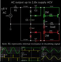
I devised an AC-AC voltage multiplier, which is powered by the incoming signal.

It will output 20 V AC sines, if you feed it 8 V AC sines. The potentiometers must be tailor-adjusted to give you a waveform that matches the one you put in.

I made the load 1.4 uA at the waveform peaks.
Current consumption is under 10 uA (avg).

You would still have to construct an oscillator that gives you 16V total voltage swing, with a current draw under 50 uA.


Transformer can't be used because there is additional limitation for the size of the solution. Initially I started experiments with LC oscillators but I had no success to get them working on low power and on such low frequency.
For the said 1kHz/20µW load, feasible magnet wire gauge and required number of turns versus core size will be the essential limitation. You didn't however specify the size constraints. For the time being, I assume that a small 1 kHz resonant transformer can almost fit the room required by the boost converter magnetics.
 

Hi,

The idea of BradtheRad is clever - doubling the amplitude can help to keep the consumption lower. The only one possible problem is that it will require tuning of the output transistors - having potentiometers and doing adjustments for individual samples is not accepted in my case. I'll give it a try with LTSpice before I go further with prototyping.

The room requirements are really tough - I need to fit the whole schematic and the battery into 3mm barrel, but the length could be up to 100mm. The best solution will be some resonant solution - piezzo, LC or something else which can generate higher voltage from 3V battery.

Thank you for your suggestions - they are really helpful!

Kind regards,
Luben
 

Status
Not open for further replies.

Similar threads

Part and Inventory Search

Welcome to EDABoard.com

Sponsor

Back
Top