Continue to Site

Welcome to EDAboard.com

Welcome to our site! EDAboard.com is an international Electronics Discussion Forum focused on EDA software, circuits, schematics, books, theory, papers, asic, pld, 8051, DSP, Network, RF, Analog Design, PCB, Service Manuals... and a whole lot more! To participate you need to register. Registration is free. Click here to register now.

1.5 KW switching regulator

Status
Not open for further replies.

meysaminter

Banned
Joined
Dec 19, 2009
Messages
59
Helped
0
Reputation
0
Reaction score
0
Trophy points
1,296
Activity points
0
Hi All,

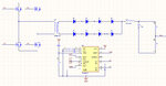
I want to build a 1.5 KW switching power supply input voltage is 80-230 v . I want to use full-bridge topology . the tl494 and sg3525 are my choice now . does any one have a shematic ?
 

Dear meysaminter
Hi
You can refer to the datasheet of SG3525 or tl494 , they suggested some circuits that you can develop them simply . did you see the full datasheet of them ?
BTW : you'll need a ferrite transformer for your aim . do you know about it's calculations ? if no , i can help you .
Wish you the best
Goldsmith
 

i really appreciate your help Mr.goldsmith . I'm from Iran too . now I'm reading the datasheets and soon I will use you experience . thanks.
 

Love to help you for the 1500w SMPS stage Use an IR1150 for drives ...Are you also getting a PFC at input stage?.
 
Thank you for the reply, is IR1150 is better than sg3525 and tl494?
 

Again Hi
It depends on your application that what IC is ok.
respect
Goldsmith
 

Dear goldsmith ,
Can you explain about the usage af ICs?

---------- Post added at 17:31 ---------- Previous post was at 17:27 ----------

Love to help you for the 1500w SMPS stage Use an IR1150 for drives ...Are you also getting a PFC at input stage?.

yes it seems to be a PFC at input
 

Again Hi
My mean is :
For example , uc3844 or3845 , designer for fly back converter , and with simple changes , we can prepare it for a simple forward converter .
and with hard changes we can use it for the other categories . BUT SG3526N , usually , designed for push pull converter or H bridge ( with some changes ) or half bridge(directly)
And each arrangement depends on your power , and the frequency of operation , and the money that you want to pay .
Best Lucks
Goldsmith
 

Fine Goldsmith,,,however ,,flyback is OK for 200-300watts.For power >1kw we need to combine flyback + feedforward ..
Alternately , go for pushpull designs which can deliver upto a few kilowatts .
For this we need to go for synchronized bipolar pulses driver ...As such 3525 or 3526 are ideal drivers .
 

Dear vimalkhanna
Hi
Yes , you are quite right about maximum power of fly back ( however i saw some continuous modes with 450W ) .
and about push pull , i think it will be ok for the powers up to 1KW . ( approx) . and about H bridge: it will be ok for very high powers . and for highes powers we can design a modular SMPS , with master slave feed back .
Respect
Goldsmith
 

ok , So full bridge topology seems to be proper for 1.5 KW SMPS .
My question is wich IC has simple designing .
 

I decided to work with tl494 .
 

Again Hi
Good choice , but can you tell us the reason ?
Best Wishes
Goldsmith
 

Mr. goldsmith , the reason is the popularity and Availability of TL494 in Iran . and the examples of this part is more than others .
 

Again Hi
Well .
As we know , it has 2 out put . and you'll need a way to drive another mosfets . e.g : transformer or mosfet drivers , such as IR21XX series .
Good luck
Goldsmith
 

Hi , I designed a simlpe circuit for full bridge topology .it is attached. PLz help me to currect and upgrade it .
 

Attachments

  • Untitled-2.jpg
    Untitled-2.jpg
    116.8 KB · Views: 129

I placed 4 mosfet drivers . and first correction attached . I am waiting for your Idea obout it .
 

Attachments

  • Desktop.rar
    157.4 KB · Views: 114

- the low side transistor current sense resistors are placed wrong
- IR2125 is non-inverting and need's to be driven by E rather than C outputs
- load resistors for TL494 C respectively E outputs are required, refer to datasheet
- you are connecting output voltage feedback directly to TL494. If you want to have galvanic insulation between input and output, the voltage feedback needs to use an optocoupler
- phase shift would be a better way for H-bridge output regulation, but doesn't work with TL494
 
I corrected the current sense resistors and working to use an optocoupler in feedback. but I dont undrestand what is C and E outputs:sad:
 

Status
Not open for further replies.

Similar threads

Part and Inventory Search

Welcome to EDABoard.com

Sponsor

Back
Top