Continue to Site

Welcome to EDAboard.com

Welcome to our site! EDAboard.com is an international Electronics Discussion Forum focused on EDA software, circuits, schematics, books, theory, papers, asic, pld, 8051, DSP, Network, RF, Analog Design, PCB, Service Manuals... and a whole lot more! To participate you need to register. Registration is free. Click here to register now.

0-5v pwm converter problem

Status
Not open for further replies.

nikhilt007

Member level 2
Member level 2
Joined
Jun 6, 2012
Messages
50
Helped
5
Reputation
10
Reaction score
5
Trophy points
1,288
Location
Mumbai ,India
Visit site
Activity points
1,559
hai
here i made 0-5 pwm converter to 0-10
i gave my 0-5v pwm i/p to an non inverting op-amp circuit (uc741)
it is working but the problem is that when i am given 0v i/p op-amp out giving 3.5v

i cant able to nullify output offset voltage

please help me


8-O
 

hai
here i made 0-5 pwm converter to 0-10
i gave my 0-5v pwm i/p to an non inverting op-amp circuit (uc741)
it is working but the problem is that when i am given 0v i/p op-amp out giving 3.5v

i cant able to nullify output offset voltage

please help me
Hi as Brian mentioned before , 741 is not a good choice for this aim . can you show us your schematic please ? then we can help you more .
But i think you'd better try with LF356 or every better op amps !
Best Wishes
Goldsmith
 
hi,

untitled.JPG
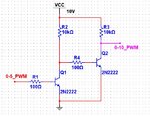
I think you can use something like this. I have put some arbitrary resistor values.
 
Last edited:

somebody sugest me a circuit for pwm 0-5v to 0-10v
Hi
I think you'd better to mention a thing exactly ! what do you mean by "for PWM 0-5 to 0-10 v " ?? is your mean you're looking for a PWM signal which has variable amplitude ? if so may i ask you what is application of such a waveform ? if you mention these parameters exactly , then i can help you in a correct path .
Best Wishes
Goldsmith
 
Last edited:

It is great that you found the solution yourself but you could at least share the solution with the rest of the members
 

It is great that you found the solution yourself but you could at least share the solution with the rest of the members


i have done it by using just only one optocoupler mct6
i given the 0-5v pwm input to mct6 and just apply to rc parellel circuit
and i am getting the result
actually mct6 contyain transistor and iam amplified my signal using npn transistor inside the mct6


for getting correct 0-10v out put make periode of your pwm as larger and increase duty cycle from minimum very slightly you will get a 0-10v varying output
and applide it across parellel rc circuit
 

Status
Not open for further replies.

Similar threads

Part and Inventory Search

Welcome to EDABoard.com

Sponsor

Back
Top