Vermes
Advanced Member level 4
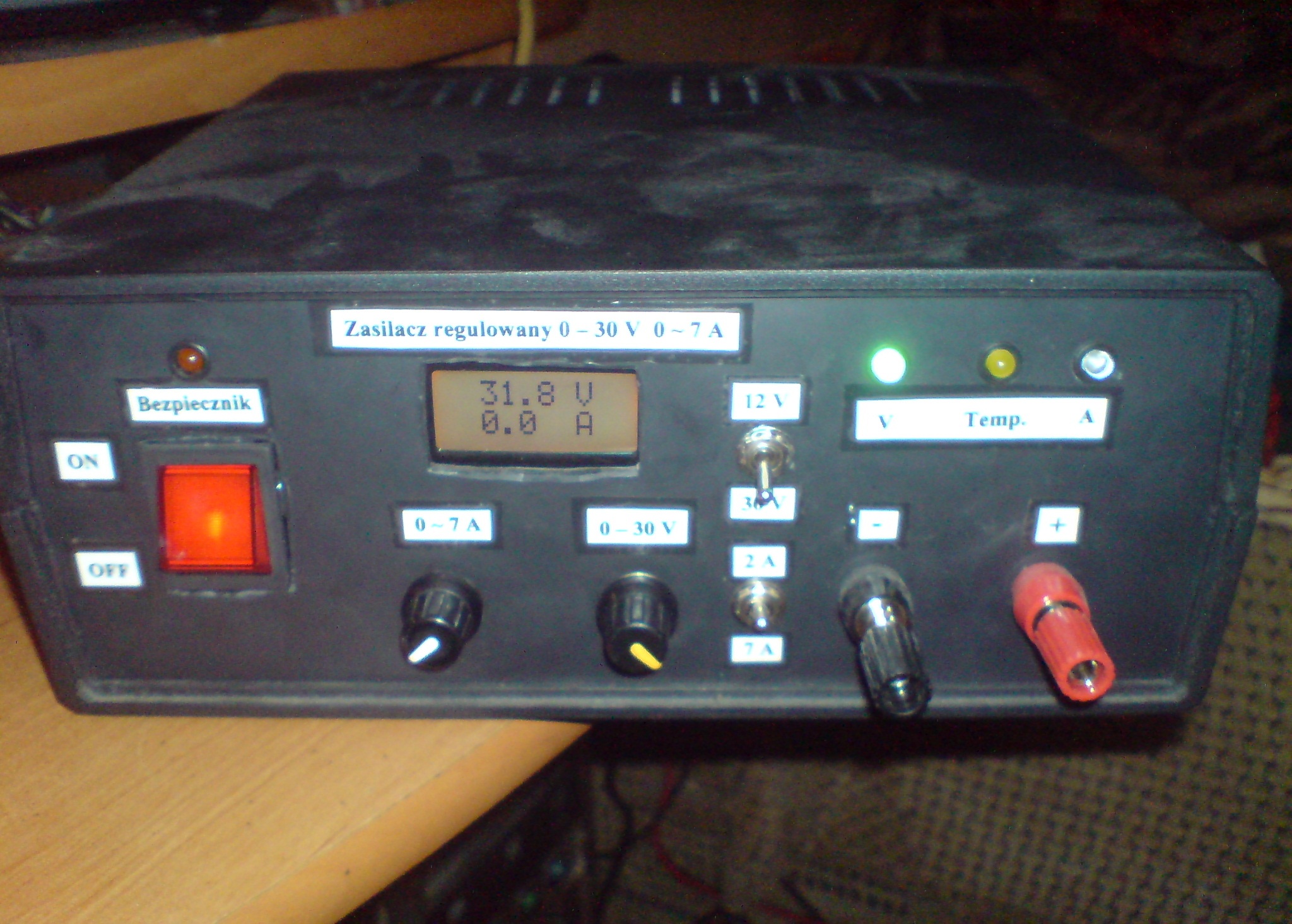
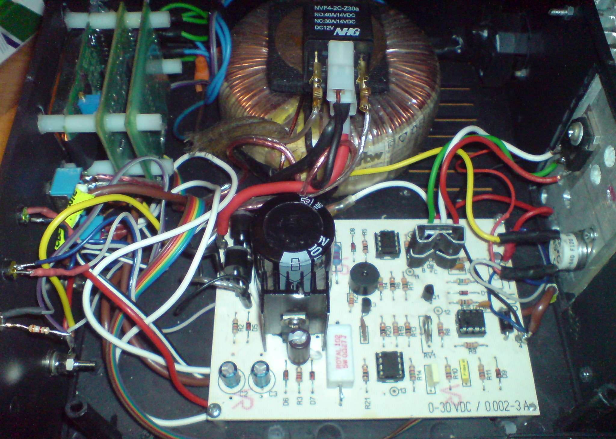
Scheme of the PCB can be found here: LINK. The project was modified by adding a small converter – 12V stabilizer (7812) to power the fan, relay and indicator on the front.
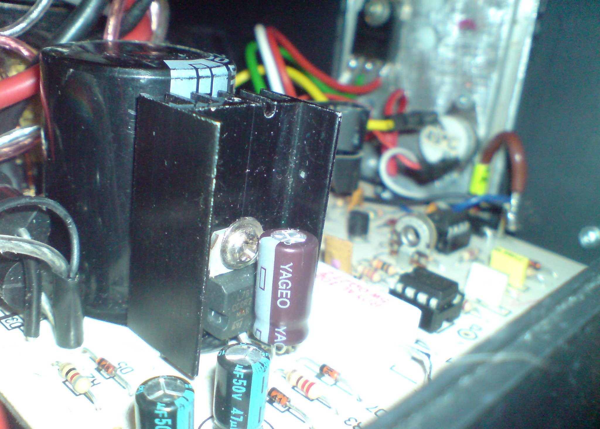
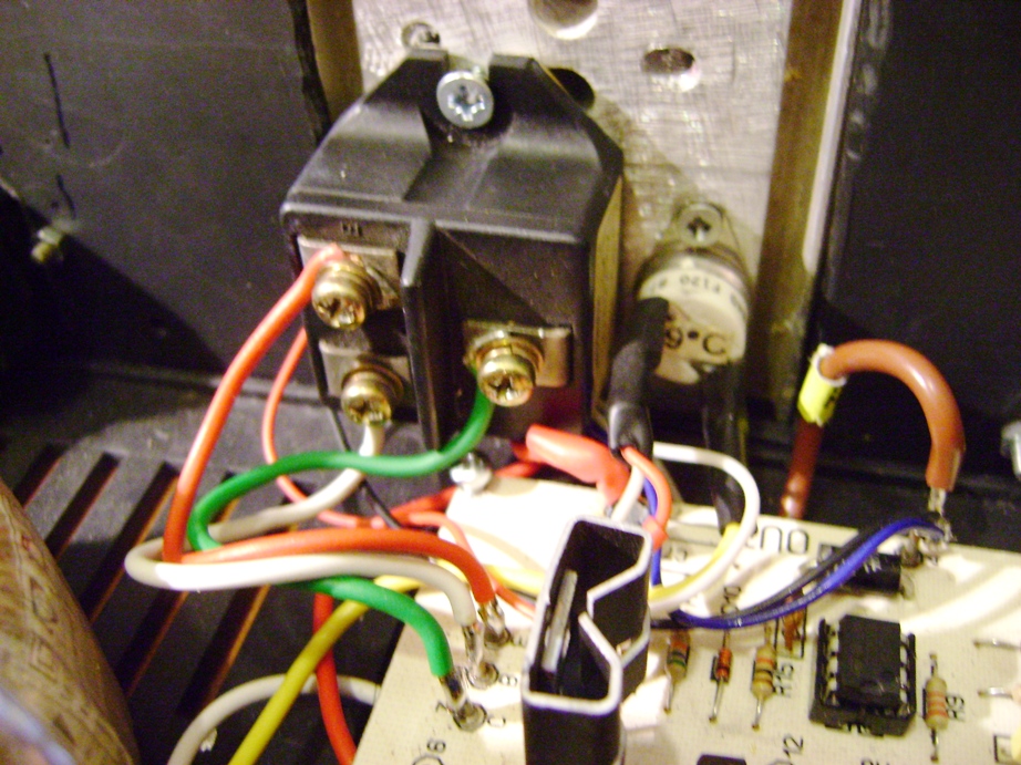
The final power transistor was changed from 2N3055 to BDW83D and control transistor 2N2219 to BD243 because it heated up too much. Switch 2A/7A was connected to the second horseshoe at the main potentiometer (not shown in the pictures).
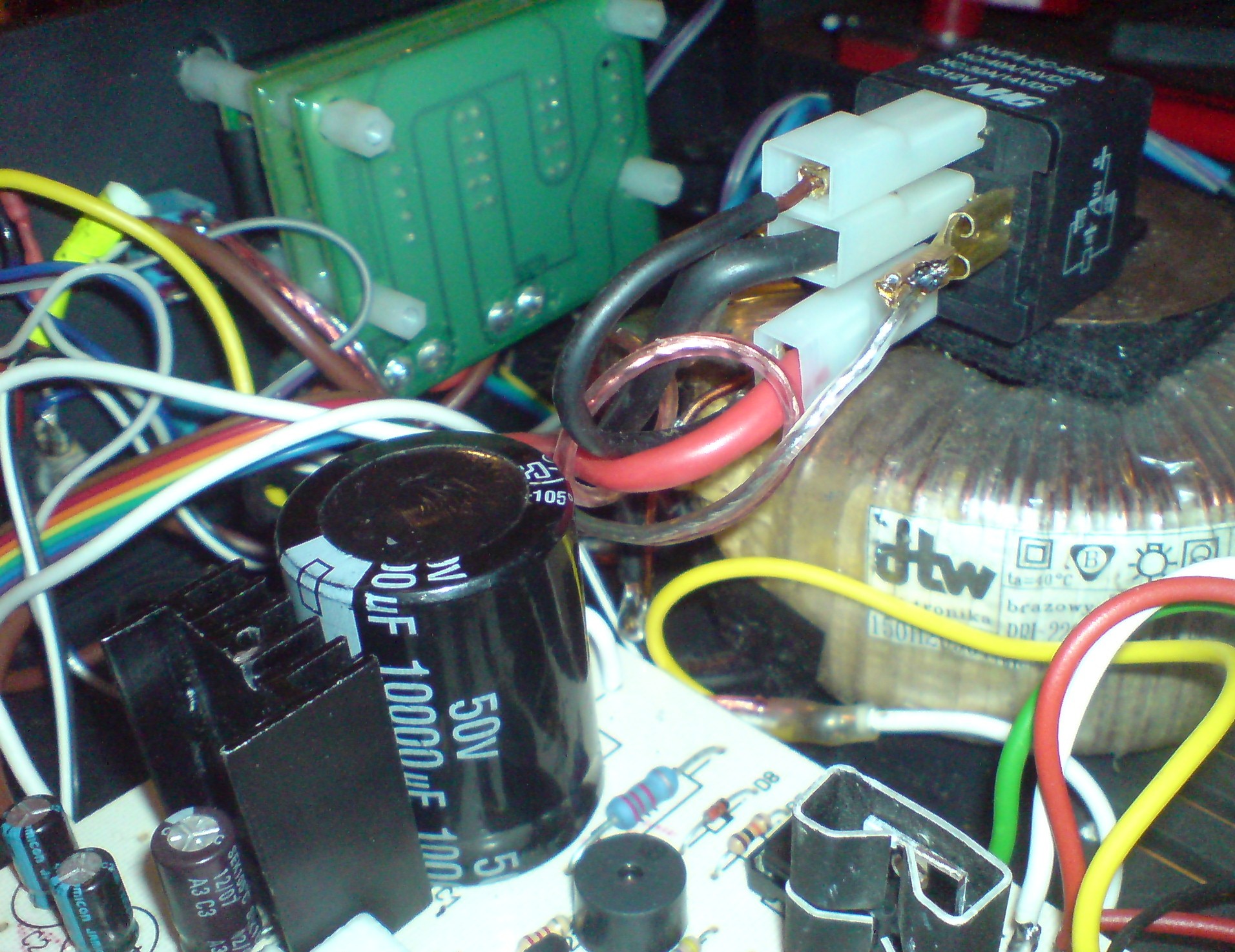
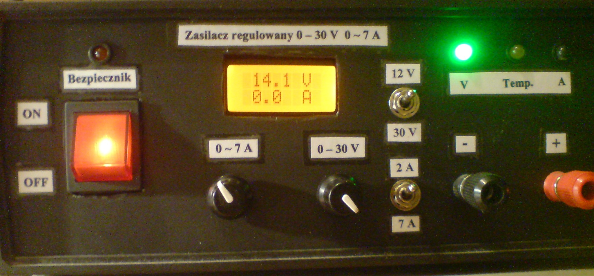
Switch 12V/30V was connected to a large relay of transformer windings (transformer from old halogens 2x 11,4V 250VA).
There is also a beeper on the board connected with the diode on the front panel, that indicates it when the set current is exceeded.
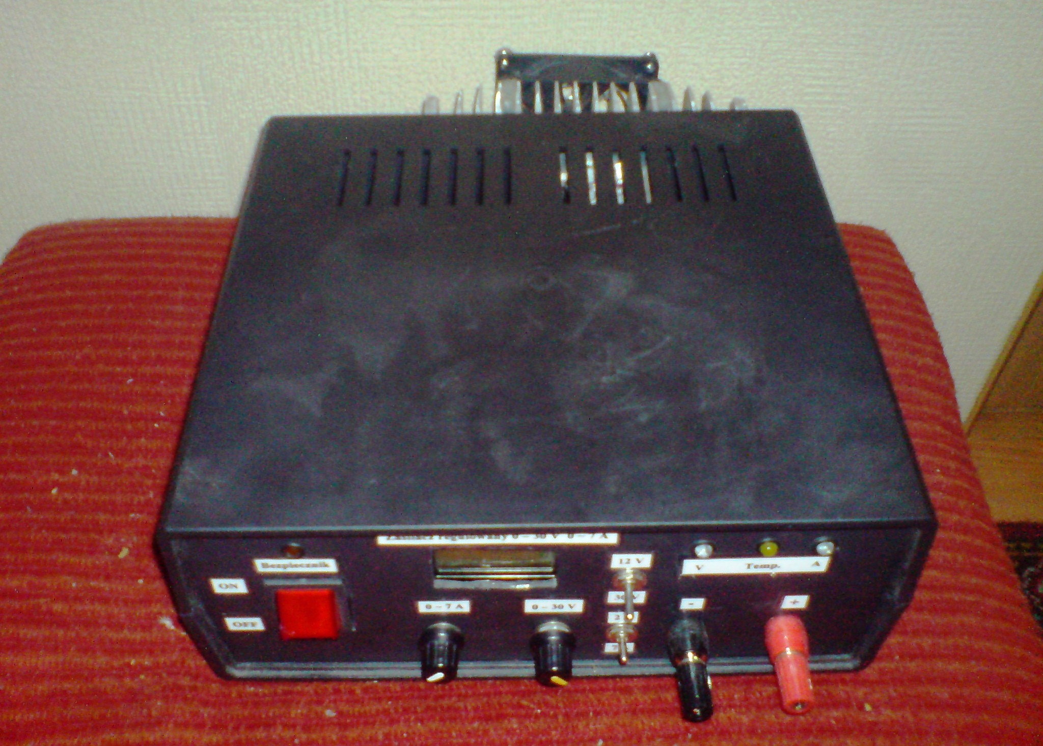
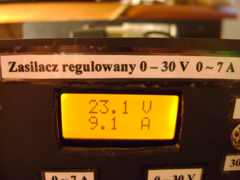
The indicator on the display 2x8 with orange backlight has set work parameters in the range of 50V and 15A.
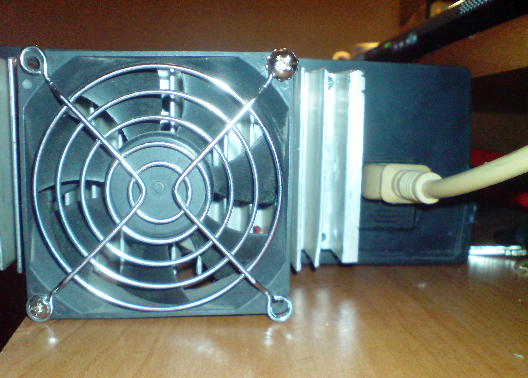
The power supply is equipped with the temperature sensor 49 degrees Celsius – after exceeding that, the fan is activated and yellow LED in front turned on.
Gallery:
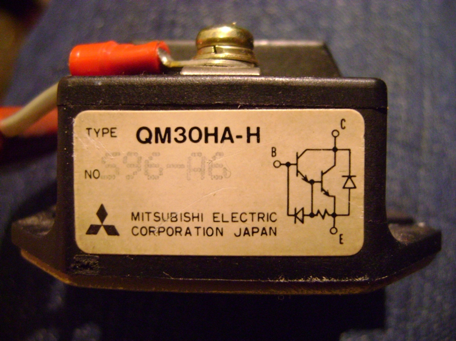
Transistor QM30HA-M Mitsubishi was added. Parameters: **broken link removed**. Few 24V bulbs act as the load.
Link to original thread (useful attachment) – Zasilacz 0-30 V 0-9 A electronics-lab - wersja poprawiona