Continue to Site

Welcome to EDAboard.com

Welcome to our site! EDAboard.com is an international Electronics Discussion Forum focused on EDA software, circuits, schematics, books, theory, papers, asic, pld, 8051, DSP, Network, RF, Analog Design, PCB, Service Manuals... and a whole lot more! To participate you need to register. Registration is free. Click here to register now.

PIC18F45K22 Digital controller Design using DAC external

Status
Not open for further replies.

A_Tareq

Newbie level 4
Joined
Apr 17, 2016
Messages
7
Helped
0
Reputation
0
Reaction score
0
Trophy points
1
Activity points
96
Hi ,

or Hi Mr. Peter (tpetar),

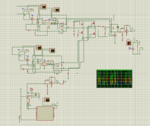
I have PIC18F45k22 with DAC MCP4922, I need to design a feedback controller for my INverter 12V Dc to out put of max 9v peak AC 50Hz, sinewave, I use LC filters and at the output to make read by PICMICROPIC 18f45k22 at AN2 channel , I use feedback gain of =0.1 and a noninverting level shifter .In my circuit I also use external ac voltage source of 0.6v peak Approx 50Hz again level shifted and at channel AN0 I make it read and then in my code I generate err signal, and then I neeed to implement the controller in C code, My Compiler is MIKRO C for PIC , I use only C code donot know good assembly,

I designed the controller for my inverter in Z domain, it works perfect in simulation with MATLAB:

here is the TF in z domain :
0.78834*10*( z^2 - 1.808*z + 0.968)
____________________________________

Z*( z^2 - 0.9583*z - 0.04167 )

my triangular or modulating signal has 10kHz freq so mosfets are switched at that freq and peak to peak is 4V, sample time for z domain in the above controller i have 100uS,

Now the Problem starts here: I could not write my C code for this Z domain TF , what Primarly I need is just to write C code for any given order( higher than
2) in Z domain, where the order of numerator is less than or equal to the Order of Denominator

I use Simulation Software Proteus before I breadboard my project.

So , you have the knowledge, so please help me with that.

Thanks

A_tareq
 

I think tpetar doesn't visit edaboard much now. He has a job at mikroe. You can contact him through mikroe forum or mikroe technical support.
 

Hi can I have anyone else in this forum who knows about this to have a look at this problem so this way I will be helped.

Thanks
 

Dear Easyrider;

Here is my proteus Schematic, and the C code , I am new in this site, (not use that much)

may be better Pics the Files it selves. My circuit in Open Loop completely works in Proteus as expected, but in Closed Loop I donot get what I expect, cuz of my Code problem;

And the the closed with the previously mentioned TF in Z domain completely works in MATLAB,

My idea is to learn how to write C code for any given Transfer function of any Order in Z domain my DAC is MCP4921, with SPI interface

Thanks.


Code C - [expand]
1
2
3
4
5
6
7
8
9
10
11
12
13
14
15
16
17
18
19
20
21
22
23
24
25
26
27
28
29
30
31
32
33
34
35
36
37
38
39
40
41
42
43
44
45
46
47
48
49
50
51
52
53
54
55
56
57
58
59
60
61
62
63
64
65
66
67
68
69
70
71
72
73
74
75
76
77
78
79
80
81
82
83
84
85
86
87
88
89
90
91
92
93
94
95
96
97
98
99
100
101
102
103
104
105
106
107
108
109
110
111
112
113
114
115
116
117
118
119
120
121
122
123
124
125
126
127
128
129
130
131
132
133
134
135
136
137
138
139
140
141
sbit Chip_Select at RC0_bit;
sbit Chip_Select_Direction at TRISC0_bit;
 
double AD_LSB,y_high, y_low , sk  ;
 
#define NUM_SECTIONS  3
double coeff[NUM_SECTIONS*5] =  { 0.9583, 0.04167 , 1.0, -1.808, 0.968 ,
                                0.0 , 0.0, 0.0, 1.0, 0.0,
                                0.0, 0.0, 1.0, 0.0, 0.0 };
                                
      /* { 0.9583, 0.04167 , 1.0, -1.808, 0.968 ,
                                0.0 , 0.0, 0.0, 1.0, 0.0,
                                0.0, 0.0, 1.0, 0.0, 0.0 }; */
 
                                
double control_gain = 10.0*0.788 ;  // gain is 10 times increased
 
 
double state[3] = { 0.0, 0.0,0.0  } ;
double*ptr_coeff, *ptr_state;
 
double input, output, yk, ADCres;
int section_count ;
 
 
void Initilalize_AD(void)
 
{  TRISA = 0x04;       // SET CHAMNNEL 2 AN2/RA2
   ANSELA.ANSA2 = 1 ;  // AN2 is analog channel
   TRISA.TRISA2 = 1 ;
 
   ADCON2 =0X8A;


    ADCON1.PVCFG0= 0;       // VREF+ = VDD
    ADCON1.NVCFG1 = 0 ;    // VREF = VSS
 
 
    ADCON0 = 0X09 ;
  }
 
  void Read_AD_Input(void)
  {
    PIR1.ADIF = 0; // A/D INT. NOT SET, i.e. not started a/d conversion
    ADCON0.GO =1; // A/D CONVERSION BEGINS
    while( !PIR1.ADIF  );
    y_high=ADRESH;
    y_low=ADRESL;
    yk=256.0*y_high + y_low;
    yk=yk*AD_LSB;
 
  }
  void DAC(unsigned int value)
  {
    char temp;
 
    Chip_Select = 0 ; // enable DAC
 
 
    temp = (value>>8) & 0x0F ;
    temp |= 0x30;
    SPI1_Write(temp);
 
    temp = value ; //send low byte
    SPI1_Write(temp);
 
    Chip_Select = 1 ; // disable DAC
  }


  void main() {


     AD_LSB =  5.0/1024.0 ;
 
 
     ANSELC = 0 ;
     TRISC  = 0;
 
     Chip_Select  = 1;
     Chip_Select_Direction  = 0 ; // CS IS OUTPUT
 
     SPI1_Init();
     Initilalize_AD();
 
 
     while(1){
 
     Read_AD_Input();
     
     delay_us(1);  // delay for using 2 channels
     
     ADC_Init();
     ADCres = ADC_Get_Sample(0);
     sk = ADCres*5.0/1024.0;
     
     input = sk - yk ;
     ptr_coeff = coeff;
     ptr_state = state;
 
     for(section_count = 0;  section_count < NUM_SECTIONS ;  section_count++)
         {
            *( ptr_state+2)   = *( ptr_state+1) ;
            *( ptr_state+1)   = * ptr_state ;
 
            *ptr_state = input + *(ptr_coeff) *( *( ptr_state+1))
 
                          + *(ptr_coeff+1) *( *( ptr_state+2)) ;
 
             input =  *(ptr_coeff+2) *( *( ptr_state++))
 
             +  *(ptr_coeff+3) *( *( ptr_state++))
 
             +   *(ptr_coeff+4) *( *( ptr_state++)) ;
 
             ptr_coeff = ptr_coeff +5 ;
 
          }
 
       output = control_gain *input ;
       //output = output*4095.0/5.0 ;
       
       DAC(output)  ;
 
        /* Skiping the Timer Interrupt , instead Using delay
     T0CON = 0XC0;    // ENABLE TIMER0, 8 BIT TIMER MODE, PRESCALER 2
     TMR0L = 246;
     INTCON = 0xA0;  // enable global and TMRO interrupt
 
     for(; ;)   // Wait for interrupt
     { */
 
     delay_us (100);
 
     }
}


Attachments

  • InverterSnap.PNG
    InverterSnap.PNG
    55.7 KB · Views: 172
Last edited by a moderator:

Hi,

I strongly recommend to use interrupt controlled regulation loop. This ensures a fixed timing.
Fixed timing is essential for filters, PID control loops. Only with fixed timing you can calculate dead_time, delay time, phase angle ....

Additionally you gain a lot of processing power for other tasks.

Klaus
 

Hi; Thanks for your advice,

The PID control for my System generates an unstable CL system, that' s why I avoided, it and secondly I just wanted to learn how to write very simple working C code for the the Z domain TF given in the First Post, I have lot of other converters where I happen to deal with them.

That's the reason, I used interrupt previously, which did not help me and I went for the simple one, with the delay to trouble shoot my code.

thanks.
 

Hi,

The delay makes things worse.
Every change in code changes response, changes the loop stability. The results are neither reliable nor easy to calculate.
Even every other process will influence the stability.


You need a fixed and known timing of AD_conversion to DA_conversion.
I recommend folowing ISR:
* start AD conversion
* write DAC with previously calculated output
* wait until ADC conversion finished
* read new AD conversion result
* calculate new DAC output
* something else.
* leave ISR

This gives a stable, low jitter delay between ADC and DAC of one interrupt_period_time + small_constant_time

Klaus
 

Hi;

As You you will see in my code pasted, I started the program actually with the interrupt, but for troubleshooting of the code I went for delay and it worked for my other programs pretty well to implement other TF's in Z domain, anyways, I still tried back with the ISR it still gives me unexpected.

I appreciate your kind advice. any thing else wrong in my code ;that implements the given TF in Z domain,

that any of you guys could point out

Thanks.
 

Status
Not open for further replies.

Similar threads

Part and Inventory Search

Welcome to EDABoard.com

Sponsor

Back
Top