Continue to Site

Welcome to EDAboard.com

Welcome to our site! EDAboard.com is an international Electronics Discussion Forum focused on EDA software, circuits, schematics, books, theory, papers, asic, pld, 8051, DSP, Network, RF, Analog Design, PCB, Service Manuals... and a whole lot more! To participate you need to register. Registration is free. Click here to register now.

Thoughts on these audio amp circuits?

Status
Not open for further replies.

Enzy

Advanced Member level 1
Joined
Mar 20, 2016
Messages
488
Helped
2
Reputation
4
Reaction score
2
Trophy points
18
Activity points
4,607
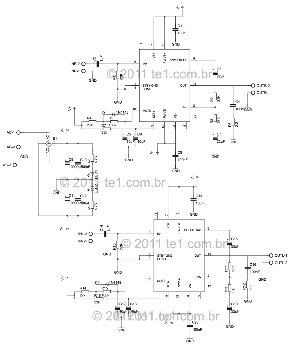
I build amplifiers as my hobby when I come in from work I am yet to build good high power amplifiers but what seems to e worst is that I can never build good amplifiers they always hum or hist or if not they always make the amplifier that its connected to lower, If its not lower then it never increases the volume so I am always trying out new circuit I want to know how does this circuit look to you guys, the plan would be to use it to increase the volume then use a tone control circuit otherwise to control bass, mid and tweeter.


want to add it to this circuit


Hi,

The first is a very basic circuit, maybe from the 70ies.

The second - as already remarked in another thread - is useless because the amplifier partname is missing.

*****
My recommendation:
Learn. Learn about designing amplifiers.
Signal amplifier to increase signal amplitude and building filters.
Power amplifiers. There are different classes of power amplifiers.
Learn how to wire signal lines and power lines of a power amplifier.

I saw some threads of you. You are searching the internet finding new schematics. And it seems you try to build them.
This is good technique.
But what I'm missing is that you go into deep with a circuit. Find you WHY there is humm or hiss. Often it's not caused by the circuit itself, but by the wiring.
Use one circuit - good or bad - and try to improve it. Check out what's happening when you use "star" connected ground wiring.
Then find out what's happening when you move the star point (to the power capacitors, to the amplifier, to the signal inlet...)

With this knowledge you may find out, that a "bad" amplifier design may generate acceptable sound quality.
Without the knowledge you may have a high quality amplifier design, but giving awful sound, with lots of noise.

If i remember right, then you said that the availability of electronic parts is problematic in the region where you live.
This makes things difficult ... at least it takes time...but take your time.

We will assist you.

Klaus
 
  • Like
Reactions: Enzy

    Enzy

    Points: 2
    Helpful Answer Positive Rating
Learn analogue electronics in general and apply this to audio.... some areas of audio are so full of misguided myths and ideas that you can end up going down a slippery slope.....

A few minutes looking a chip amp pin outs should find you the amp device in the second schematic, possibly a Ti device.
 

Doug Self has a couple of books on audio amps that are no nonsense.
"Small signal audio design" is worthy, as is his book on power amp design.

And, yea you need to learn electronics in a more general sense there is nothing magic about audio.

Regards, Dan.
 

The power amplifier you showed here is probably the TDA7293 you showed in another thread. Its part number and its supply voltages should be shown on your schematic. Its datasheet tells you that the ratio of R2 and R3 set its voltage gain then it is easy to increase its gain with those resistors instead of adding an old preamp circuit.
 

The power amplifier you showed here is probably the TDA7293 you showed in another thread. Its part number and its supply voltages should be shown on your schematic. Its datasheet tells you that the ratio of R2 and R3 set its voltage gain then it is easy to increase its gain with those resistors instead of adding an old preamp circuit.

Thanks for that info so you think that increasing the gain from the chip amp itself is sufficient? Also I need tone control with each circuit I build so I would still need to add that but I wouldn't want it to reduce the overall gain too much or at all I dont know any good schematics really.

- - - Updated - - -

Hi,

The first is a very basic circuit, maybe from the 70ies.

The second - as already remarked in another thread - is useless because the amplifier partname is missing.

*****
My recommendation:
Learn. Learn about designing amplifiers.
Signal amplifier to increase signal amplitude and building filters.
Power amplifiers. There are different classes of power amplifiers.
Learn how to wire signal lines and power lines of a power amplifier.

I saw some threads of you. You are searching the internet finding new schematics. And it seems you try to build them.
This is good technique.
But what I'm missing is that you go into deep with a circuit. Find you WHY there is humm or hiss. Often it's not caused by the circuit itself, but by the wiring.
Use one circuit - good or bad - and try to improve it. Check out what's happening when you use "star" connected ground wiring.
Then find out what's happening when you move the star point (to the power capacitors, to the amplifier, to the signal inlet...)

With this knowledge you may find out, that a "bad" amplifier design may generate acceptable sound quality.
Without the knowledge you may have a high quality amplifier design, but giving awful sound, with lots of noise.

If i remember right, then you said that the availability of electronic parts is problematic in the region where you live.
This makes things difficult ... at least it takes time...but take your time.

We will assist you.

Klaus

ITs true I need to learn from scratch how audio electronics work, I do a full time job in Industrial electronics within the factory industry but I prefer this type of electronics I like to build Amplifiers and Inverters I do try to inprove circuits that I see on the internet but its so frustrating when I dont have the proper knowledge on how to do it properly and I dont have much time to actually do proper studies thats why I ask so much questions in these forums. I should really spend time to fix amplifiers that I build with issues though I tend to not want to spend alot of time on one particular circuit and I realize that its not a good thing but if I happen to fix the circuit by fooling around with parts I wouldnt understand why It worked so I think I would still be at square 1.
 

Thanks for that info so you think that increasing the gain from the chip amp itself is sufficient? Also I need tone control with each circuit I build so I would still need to add that but I wouldn't want it to reduce the overall gain too much or at all I dont know any good schematics really.
The TDA7293 amplifier in the datasheet has a voltage gain of 33.5 times which is more than most amplifiers. Why is the level of your signal source so low?
A tone controls circuit usually has a voltage gain of 1 (no gain and no loss) so that it can boost or cut highs and lows by up to 3.5 times.

Go to **broken link removed** where there are many audio articles and projects including amplifiers and tone controls.

ok then ill check it out, It normally sounds ok it isnt low but one I use a ready made amp and compare it to mine even lower wattages like 18 watts they always have more volume than the ones I build, but since i know understand that the resistors at pin 2 and pin 3 can be changed to increase the gain then ill try that I am wondering if I there is a limit to the value resistors that I should try though meaning I shouldnt go above or below specific values to increase the gain.
 

Of course there is a limit to resistor values. R3 is 22k now. If it is increased then the gain will be more. 47k= double the gain. 68k= 3 times the gain. 91k= 4 times the gain.
Also make R1 the same value as R3.
 

Of course there is a limit to resistor values. R3 is 22k now. If it is increased then the gain will be more. 47k= double the gain. 68k= 3 times the gain. 91k= 4 times the gain.
Also make R1 the same value as R3.

Even though I doubt I will ever bring it up so high but its good to know.... is 4 times gain the highest? also both R2 and R3 can increase or decrease the gain so I assume both would be doubled similarly only thing is that I realize R2 should be decreased to increase gain. So If I add a 340 ohm to R2 and a 47k to R3 that means the gain would be 4 times more?

Also What if I plan to only change one resistor but I change R2 instead and keep R3 at 22k, would I still need to change R1 or keep it as default.

What I think I will do is practice using one chip at a time, this chip has some bridge modes ect which I dont understand as yet, also when I connect this chip I have never used the mute and stand by features I have always tied them and connect it directly to vcc. If I dont do that then I get no sound because I dont normally know how to connect them.

- - - Updated - - -

between the TDA7293 and TDA7294 would you consider one of them to be better meaning if it would be better for me to use 1 or the other?
 

R3 can be much higher than 91k but when the gain is increased then the distortion and noise are also increased.

R2 is in series with capacitor C2 to ground. If the value of R2 is reduced to increase the gain then the value pf C2 needs to be increased so that the amplifier amplifies low frequencies.
The datasheet has Application Suggestions that lists the suggested values on the schematic, the function of each part and what happens if its value is larger and what happens if its value is smaller.

The TDA7293 has Clip Detection that is not available on the TDA7294.

I was thinking about trying the clip light feature, would I just connect a led to pin 5? anode to pin 5 and probably a 1k resistor from cathode to ground
 

I was thinking about trying the clip light feature, would I just connect a led to pin 5? anode to pin 5 and probably a 1k resistor from cathode to ground
It seems that you do not look at and read the datasheet.
The schematic of the amplifier IC shows an N-channel Mosfet with its source at ground and its drain at pin 5. The Electrical Characteristics says that the clip detector pin 5 should have a 10k resistor to +5V (for it to send a logic low to an alarm circuit). No LED. The maximum allowed voltage at pin 5 can be +120V but they forgot to say its maximum allowed current. The 10k resistor from pin 5 to +5V will have a current of only 0.5mA so if you put a 1.8V red LED in series with a 75k resistor to +40V for a current of only 0.5mA then the LED will be very dim. The datasheet says that the duty cycle of the clip detector is low so it will make the LED appear even dimmer.

Maybe pin 5 will survive a current of 20mA then a resistor in series with the LED to +40V can be 2K but the heating in the resistor will be 0.73W so a 1W or 2W resistor should be used.
 

no wonder I have never seen a schematic where someone has used it before they normally use external clip detector circuits .

Is there a way to know what size heatsink to use on the chip? Also the types of alluminum I have at my disposal are like 14 gauge and they are flat I normally use rivets to place more than 1 together probably just bending them in a U shape.
 

We have heatsink manufactures like Wakefield who make extruded aluminum heatsinks with many fins for a high surface area. Their many heatsinks are listed with their thermal resistance and dimensions in their catalog. The datasheet mentions that the max thermal resistance of the chip to its case is 1.5 degrees C per W so with a 30 degrees ambient the IC plus thermal grease of 0.5 degrees C makes 2 degrees temperature rise per heating Watt. Select a heatsink with a thermal resistance of 2 degrees C per W then the total thermal resistance is 4 degrees C per Watt. If the ambient air is 30 degrees C then the 150 degrees max chip temperature is reached when the chip dissipates 30W. The IC is about 60% efficient then the output power is 45W.

The datasheet shows how a circuit using extra parts can share the heat and allow a higher output power.
 

Ok as It comes on the volume control what do you recommend I often just see persons use a pot of various values placed before the signal input to the amplifier to control the volume do you think thats how I should do it when building amplifiers?

I actually build the TDa7293 amplifier in stereo and I increased the gain I increased R1 and R3 b using 100k resistors.
 

Your gain is too high for a power amplifier. For that much gain you should use an additional preamp so that the power amplifier has enough negative feedback to reduce its distortion and noise. The very high gain of the power amp also reduces its high frequency response. What is your signal source for its output level to be so low?

Yes, a volume control should be at the input to an amplifier. The volume control should have an audio taper (usually marked "A", not "B" which is linear) and have a resistance that is about 1/5th the input resistance of the amplifier. Use 10k ohms.
 

I always use laptops as the input source, with the gain it had originally its now really low when used in doors but when compared to other amplifiers its significantly lower has less mid range frequencies, since I replaced the resistors I havent gotten a chance to turn it up but I will remove the resistors and try probably a 47k or 50k .

Also how would I know the input resistance of the circuit to know that value pot to use as volume control, is it as simple as just doing an ohms test across signal in and gnd.

I have my eyes on a PWM circuit that I will try next Ill post soon to get some feedback on it, I wanted to just send the link to the datasheet but seems I cannot post links here :(
 

also what are your thoughts on speaker protection circuits or input protection, is it neccessary to include them in amplifiers that I build?
 

The datasheet says the minimum input resistance of the TDA7293 is 100k ohms and you have a 100k resistor R1 parallel to the input so the input resistance of your amplifier is 50k ohms.
Texas Instruments have some class-D amplifier ICs that use PWM for good efficiency. They do not need huge heatsinks like class-AB linear amplifiers so their packages are tiny surface-mount ones.

- - - Updated - - -

also what are your thoughts on speaker protection circuits or input protection, is it neccessary to include them in amplifiers that I build?
Many power amplifiers detect a DC voltage in the output then disconnect the speaker to avoid damaging the speaker with DC from a failed part.
Some amplifiers have a clipping LED to warn you that the clipping distortion might burn out a tweeter.
 
  • Like
Reactions: Enzy

    Enzy

    Points: 2
    Helpful Answer Positive Rating
Status
Not open for further replies.

Similar threads

Part and Inventory Search

Welcome to EDABoard.com

Sponsor

Back
Top