Continue to Site

Welcome to EDAboard.com

Welcome to our site! EDAboard.com is an international Electronics Discussion Forum focused on EDA software, circuits, schematics, books, theory, papers, asic, pld, 8051, DSP, Network, RF, Analog Design, PCB, Service Manuals... and a whole lot more! To participate you need to register. Registration is free. Click here to register now.

Would like some ideas for a 100W RMS power supply

Status
Not open for further replies.

Brondog

Newbie level 5
Joined
Sep 24, 2015
Messages
10
Helped
0
Reputation
0
Reaction score
0
Trophy points
1
Activity points
128
Hello,

I am rediscovering this fascinating world of electronics and DIY things recently and decided to do something with my spare time. I decided to adapt some old car speakers and an amplifier into my new PC sound. I mean, how hard can It be?
I think it will be something like this:
P2 plug -> amp -> speakers

It IS supposed to be this simple, right? I'm already reading and making the design for the boxes in which I will hold the speakers already but at the moment I'm only having trouble on one simple thing, the reason I came here to beg for your knowledge:

The Power Supply Unit!

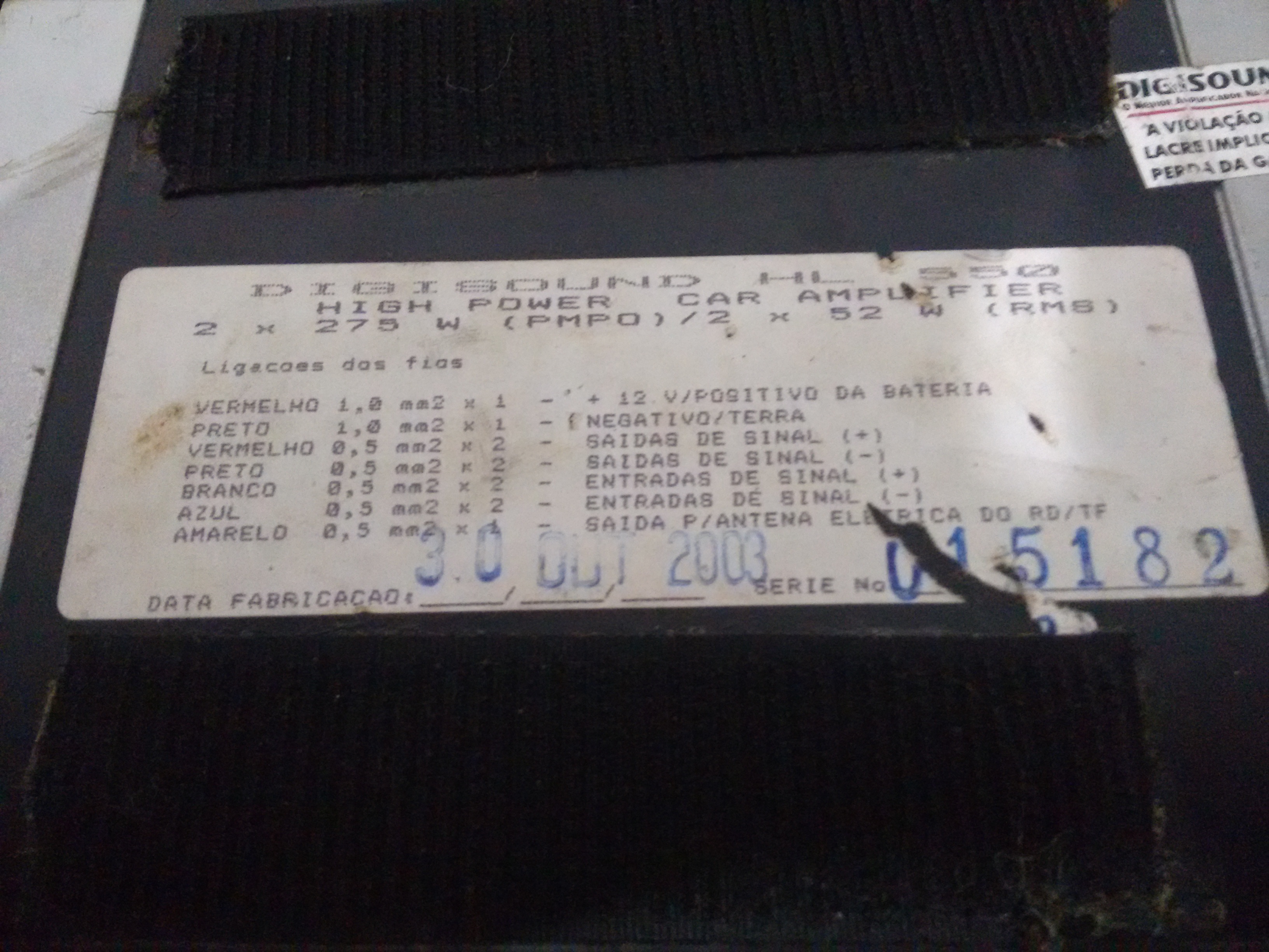
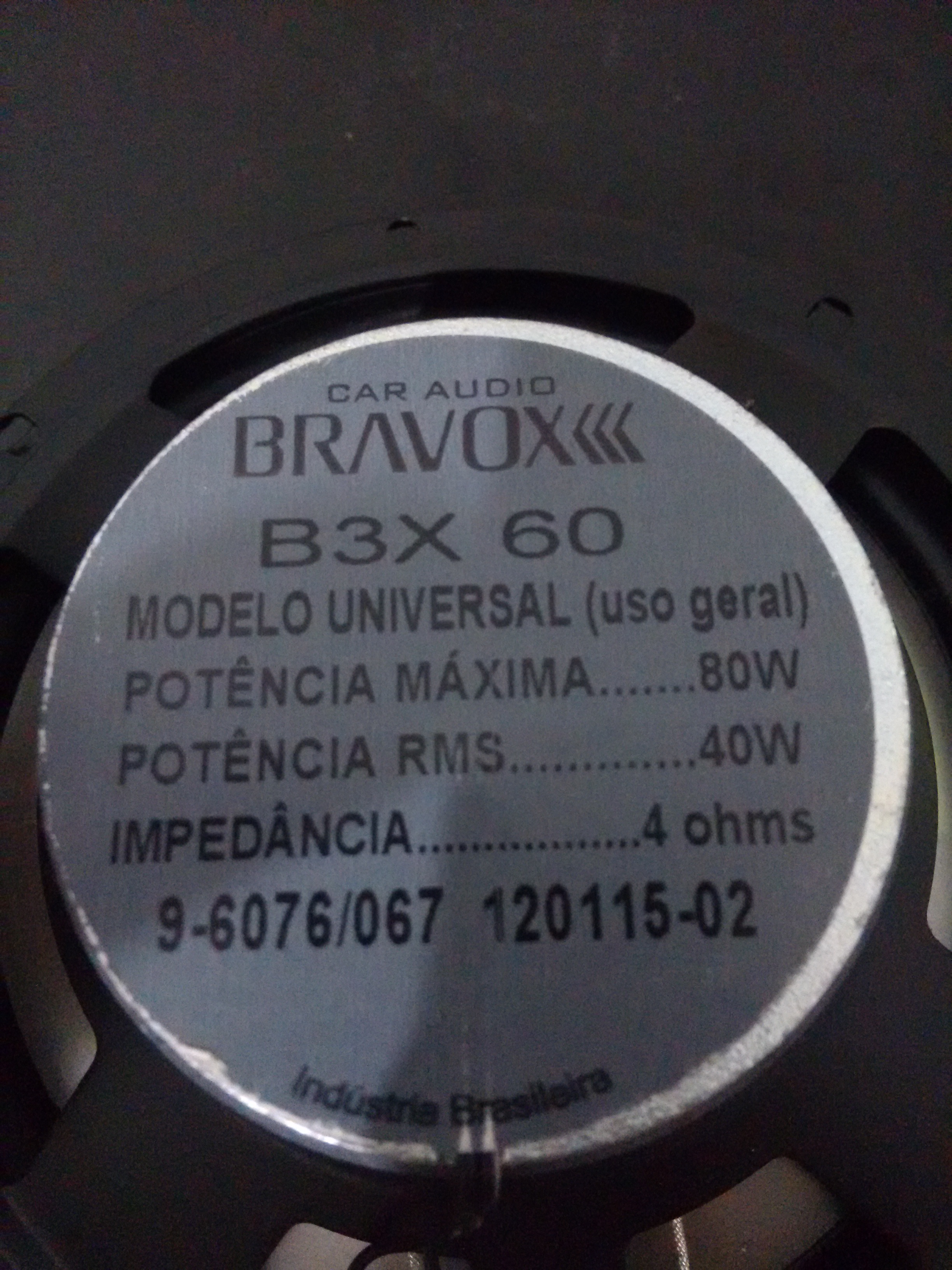
To be honest, this is by far the hardest thing to plan (and make) in this entire little project. My speakers are 25W 4 ohm each and the amp is 2 x 52 W RMS. Since it's a dual channel so 2x 52 = 104W RMS, right? (Yeah, I know the speakers could be better but I got them for free).


So my problem here right now is how will I make a good PSU for this little guy? I've heard I can't use a SMPS (switched mode power supply) for sound aplications or there will be some noise on the signal.
The problem is that creating a 100W linear power supply will cost an absurd price with a 127V/12V at 10A transformer! The transformer will cost R$105,75 to be exact and will weight almost 3 kg! :cry:


So I was wondering: the only kind of PSU I've ever done was the common:
transformer, rectifier, capacitor, LM7812
kind of PSU. A simple linear one.

Can some good soul give me an example on how to get a cheaper yet effective project? Also, will it be okay for the PSU to be constantly working on it's limit like I'm planning it to or should I have an even more capable PSU so it will last longer?

Thank you so very much and sorry for bothering you! :D
 

If you are rating the PSU for the amplifers, 50W into 4 ohms, V^2/4 = 50, V^2 = 200, so V =~14 V RMS, or 40V P-P, so you need about +- >20V from your power supply at current of 5A for both amps. But this relies on the reservoir capacitor carrying the charge over from peak to peak. This is because your 50W amplifier will at the best be only 60% efficient, so for 50W out you will need at least 50 X 100/60 W in = 83W or 160 W total plus a bit more. No way around it. So your price for your transformer is too low or try and buy a cheaper one.
So for 24V out of the PSU, 24/1.4 = 17 Vrms secondary voltage, so a pair of these would be good value :- **broken link removed**
Frank
 
Hi,

First decide what voltage you need.

SMPS for audio. No problem with a good, constantly switching SMPS with high switching high frequency.
There shoud be no audible noise. The switching frequency and it's harmonics are far above audible frequencies.
If you can hear something, then it is caused by a bad regulation or interference.
Both should be avoided by good quality SMPS.

A LC low pass filter may further improve power supply noise.
Use low ESR, high frequency electrolytic capacitors, maybe paralleled ceramic capacitors.

Klaus
 
Two 25W speakers will draw 50W total (theoretically). 5A at 10V.

Music does not draw full power on every single waveform. Most of the time you can get by with a lower wattage transformer.

What will help is to put an oversize smoothing capacitor at the output, to provide full amplitude through the moments of loudest volume.

If you are a purist, you will of course want the transformer to be full power.
 
You should start by telling us the model and post the datasheet for the amplifier. 2 x 52W might be into 8 ohm speakers at a horrible 10% distortion or it might be "music power" for only a moment and not continuous. Maybe you amplifier cannot drive 4 ohm speakers.

You must tell us if the amplifier is class-AB and wastes a lot of power getting hot or if it is an efficient cool class-D design. Many class-AB amplifiers with max power of 104W with low distortion produce 56W of heat so the power supply must produce 160W for the 104W amplifier. A 104W class-D amplifier might draw 134W from the power supply.

You said 12V so the high power car amplifier already has a SMPS in it to boost the 12V to a much higher voltaqe. This SMPS is not perfect so it will use extra power from the 12V. You might need 200W at 12V which is 16.7A.
 
I got online earlier today but didn't have much time to reply to you all. Sorry for my silence.

Well, I just saw that Audioguru wanted the datasheet of the amplifier. Unfortunately there is no available datasheet for it. I took a picture of it tough in case anyone want to see it:


The stuff written in portuguese is the cable management. At the bottom end of the sticker there is the manufacturing date. Yes, it's pretty darn old.


Anyway, I was thinking about what you guys said all day. I was considering making a SMPS after I read that a high frequency switching won't induce any audible noise but when I started looking around for schematics on how to make them it all got so over my head that made me realize I just don't have what it takes to plan and build my own.
Also, what BrastheRad said is true: I'm kind of a purist. Not only because I like to get most out of every penny I invest on my stuff but also because I'm a broken college student and also because


I JUST GOT MY HANDS ON A COUPLE 40W RMS 6" SPEAKERS AND I'M SO HAPPY! :grin: (sorry for shouting, I'm just excited about it!)

Anyway, chuckey got me kind of worried. I was already worried about the price of 100W PSUs but now he told me to plan a 160W one and I'm starting to reconsider my little project. It might be a little bit too expensive if I end up needing to overprice/overpower it even more.

Any kind of advice would come handy!

Finally, I'd like to ask you guys anyone would be kind enough to provide me with schematics for my PSU. I'm so used to make simple ones with a 1N4004 rectifier bridge, a simple electrolitic capacitor and a LM78xx (usually LM7805). I just realized how lost I am when I saw that LM7812 are 1W regulators.
Actually, if I am to make a linear PSU, just the parts list would be enough since the schematics are always the same. If instead someone is willing to be nice enough to believe me capable of building a SMPS I would need the whole thing (schematics + parts list).

When I start to swin in these waters again I always remember why I had the duality of love/hate so strong when I was an engineering student! :lol:

Anyway, thank you all for your thoughts!
 
Last edited by a moderator:

Update on a new idea I jsut got:

Hello again, guys!

A friend of mine just gave me the idea of using a Toroidal Core transformer, stick a rectifier on the exit and get a 20V 4400uF capacitor in the exit and call it a win. What do you think?

Thank you!
 

A friend of mine just gave me the idea of using a Toroidal Core transformer, stick a rectifier on the exit and get a 20V 4400uF capacitor in the exit and call it a win. What do you think?

Thank you!

Yes, a time-honored power supply method. Toroids are increasing in popularity.

Do you have access to a car battery? Can you hook it up to your amplifier? Can you measure the Amperes drawn from the battery as you play bass-heavy loud music?

That is really the test you need to make, to determine the watt rating for your power supply.
 
I'll try to check this one ASAP.

The problem is that I have a test on Tuesday so I'll have to halt this little thread of mine until then :'(

In the meantime, I'll be waiting for the amplifier's manufacturer to reply my email in which I request it's datasheet and ask for the correct psu power.

Thank so very much for everyone who have helped me so far. I'll kick *** on that test and I'll be back by Tuesday night with responses (hopefully) and some more tangible plans.

Have a good weekend and an awesome new week! You guys form an amazing community that revived in me the desire to make awesome things again with electronics!

YOU ROCK! :D
 

The label on the amplifier tells all (and more!). Its a car amplifier so it needs 12- 14V @ 10+ amps. The cabling details are wrong, it says that you should use 2mm cables for the +- 12V, much too thin, you need 4 or better 10mm cables.
Toroids are really good but are expensive, they cost more then conventional transformers. A really cheap way of getting a big mains transformer is to get one from a dumped microwave. They have a 230V bobbin and a 800V bobbin, so you strip the 800V winding off and replace it with a 11V winding. People often do this to make a spot welding transformer, where they need 2V @ 400A. The only down side is the transformers are huge and heavy. Use a Google search to find pictures to see if the size puts you off.
Frank
 
But wouldn't a normal EI plates transformer generate noise? Well... I do like the idea of doing things cheaper though :grin:
 

If you user a multimeter to measure the current required by the amplifier when it is playing bass-heavy music then it will not be accurate because a low frequency speaker resonates with a high impedance at low frequencies then it draws less current than at other frequencies.
Also, if it is a digital meter then the music would make its numbers jump around all over the place.

A 4000uF filter capacitor is much too small for 10A+. Use 22000uF or more.
 
If you are familiar with switch-mode supplies, you can go to the power integrations website, and design your self 2 x 50W psu's, each 25V say, put the outputs in series to give you a split supply, 5A peak each, and some large o/p electro's.

You can use the top-switch series devices for a forward or flyback design, there are plenty of app notes etc....
 
design your self 2 x 50W psu's, each 25V say, put the outputs in series to give you a split supply, 5A peak each.
Why duplicate many of the parts that are in the amplifier?
It is a high power amplifier for a car, it is powered by 12V at a high current and it already has a SMPS in it.
 
I really like the idea of making a SMPS. I like the idea because they're cheaper.

The problem is: I have no idea how to make one. I know the very basic principles of them but I don't have any idea on how to create one. They're so out of my league that I get lost just by reading how to start calculating them! :lol:

Also, there is the problem that the real use I need for my PSU is not to serve as an amplifier for my speakers, it just needs to power the amplifier, which works in the 10~14V range exactly because it is a car amplifier.

So, at the moment my greatest doubt is the power my PSU needs to have (I think I'll need 15~20 amps @ 12V) and the cheapest way to do it. The cheap part is pretty though right now since Brazil is in a big recession and the dollar is pretty expensive right now (U$1,00 = R$4,00) which makes importing anything pretty much impossible.

Also, I just read as I was writing this response that the alternator supplies not 12V but 14V to the system. Should I build a 14V PSU instead?

BTW, I opened the amplifier to check inside to see if I could take some pictures of it to show here but the pieces that are screwed to the chassis for cooling have thermal paste over them and unfortunately I don't have any to apply so I won't disassemble it this time. Maybe if you guys want I might go downtown, buy some, take the pictures and then apply some more.

Anyway, that's it for the time being. Thank you all so very much!
 

A SMPS uses a special transformer, special driver IC and special Mosfets that you probably will not find in your country. The SMPS in your amplifier steps up the 12V (14V) car battery to about 50V for its amplifiers.
DO NOT take the amplifier apart to take photos. Photos will not say its actual high voltage or if it is +50V or +25V and -25V. You already know it needs to be powered from 12V-14VDC at 10A+.
 
DO NOT take the amplifier apart to take photos. Photos will not say its actual high voltage or if it is +50V or +25V and -25V. You already know it needs to be powered from 12V-14VDC at 10A+.

Can I double thank you for this? I almost thought it was a good idea. Thank you for not being hue and stopping me from having a big trouble for no outcome.

Also, thanks for telling me more about the inner workings of a SMPS and explaining why I would probably not be able to assemble one by myself.

I found a good 12V/20A transformer at a reasonable price so I'll probably just buy it, do the rectifier bridge (probably going buy one already made or will make one with 1N4004) and I'll buy a capacitor and I'll call it a win. Unless, of course, if a better idea come up.

By the way, as for the capacitor, I wanted to ask (maybe?) one last question:
I found some capacitors of 22000uF 50V. I found some formula online to calculate the capacitance needed for a capacitor on a linear PSU and I believe this is enough. Am I right? Formula:
C= f * ( Vpeak² - Vmin² )
Where C is capacitance, f is circuit frequency, Vpeak is the peak voltage and Vmin is the minimum voltage on the circuit.


Want some pictures of the completed project after it's done? :grin:
 

A transformer with a 12VAC output will have a peak voltage of (12V times the root of 2) 17V and the bridge rectifier and capacitor reduces the smoothed DC output to 15VDC which is a little high. It will be maybe 16VDC when the amplifier is not blasting. You can drop the peak voltage 1.5V with two series power diodes between the rectifier bridge and the filter capacitor.

Does your amplifier have a fuse in it?
 

Does your amplifier have a fuse in it?

Yes. It's a car fuse on some kind of conector, in series with the cable. I just think it's weird that the fuse is only 10A. Also, will I need to get some diodes in series to lower the voltage?

Thanks! You're awesome! :D
 

We do not know anything about your amplifier whether its circuit is class-AB that wastes battery power making heat or is class-D that is efficient. A 10A fuse and a 14V power supply will allow a class-AB amplifier to produce a total output of about 90W RMS (45W per channel). A class-D amplifier might produce a total output of 120W (60W per channel).

Wait a minute. Car amplifiers have 4 channels for front and back stereo speakers. Maybe each of the 4 channels is class-AB and produces about 23W into a 2 ohm speaker at VERY high distortion. Then it would produce about 14W with low distortion into 4 ohms.
 

Status
Not open for further replies.

Similar threads

Part and Inventory Search

Welcome to EDABoard.com

Sponsor

Back
Top