Continue to Site

Welcome to EDAboard.com

Welcome to our site! EDAboard.com is an international Electronics Discussion Forum focused on EDA software, circuits, schematics, books, theory, papers, asic, pld, 8051, DSP, Network, RF, Analog Design, PCB, Service Manuals... and a whole lot more! To participate you need to register. Registration is free. Click here to register now.

How to know value of this coil??

Status
Not open for further replies.

ahmad_abdulghany

Advanced Member level 4
Joined
Apr 12, 2005
Messages
1,206
Helped
102
Reputation
206
Reaction score
22
Trophy points
1,318
Location
San Jose, California, USA
Activity points
11,769
how to read a coil value

Hello all,
concerning the Rx here:
**broken link removed**

Does anyone konws how did he model that coil on board? it's used together with a 100nF to tune the frequency of the Rx...
How to make similar coils with different values?

Thanks in advance,
Ahmad,
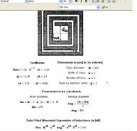
 

coil inductance produce 88mhz

Hi
search edaboard you can find on board inductor formula.
L depends tank frequency. you must measure tank freq.
regards
 

pcb coil design

Can not post the link right now, but there is a paper by mohand
 

www.comax.uk.com/wire_gauge_chart.htm

You should read AN192 and AN193 application notes from Philips. But as a simple approx. calculation you can consider LC tank composed from L and surrounding capacitors (4.7p, 18p and a trimmer 22p in the mid range) together with internal varicap capacitance. IF frequency is low, about 75kHz so you can assume that oscillator frequency is the same as input frequency.
From app. notes this inductance is about 56nH but may be different in your case.
100nF capacitor is not the part of tank circuit it is blocking capacitor.
 
how to know value

I must forget to see that, but it's not what i'm asking about,
i'm asking about the coil on board! how to model it?

Thanks for help,
Ahmad,
 

Hi,

If you wish to computer model the printed spiral inductor, you may use Sonnet planar EM software (they have a free version, **broken link removed** but I do not know if spirals are covered in the Lite) or Ensemble from Ansoft, I think they also have a free version (SV Student version).

But you can also calculate the spiral inductance on-line, see URL:

http://smirc.stanford.edu/spiralCalc.html and at the bottom you find the link for Mohan's paper:
http://smirc.stanford.edu/papers/JSSC99OCT-mohan.pdf

Regarding the lumped coils data in your FM receiver link, the SWG is used in the UK and the AWG is used in the USA for wire sizes. See link:

http://www.comax.uk.com/wire_gauge_chart.htm

and the No 18 SWG means a wire diameter of 1.219mm. The 5mm former means that you wind the 1.2mm wire onto a cylindrically shaped material like a piece of woodstick or a pencil the outside diameter of which is 5mm. You wind the 6 turns on it , then remove the former because such small coil made of 1.2mm wire is self-supporting.

I hope this helps

unkarc
 
hi
see that
i found it in edaboard.

this post is started by you.
but i think you want to analyze and simulate it.
regards
 

Borber said:
Old Appcad for DOS has option for spiral PCB inductor calculation.

h**p://www.hp.woodshot.com/

download appcadcl.exe and unpack it

Regardless the coil on board design, I downloaded both DOS version and Windows version and it's amazing program indeed contains alot of useful things,

But i didn't find the spiral designer tool in the Windows version, also couldn't run the DOS version under Windows XP..

Any comment?!
Thanks,
Ahmad,
 

Hi,

The old DOS version is a self-extracting exe file, it is advisable to make a separate folder for it. When you run it, you will find the appcad.bat among the extracted files, and to use the program you have to run appcad.bat!
I just checked it in XP and it runs in the opening DOS window! (There is a Readme.bat file also included for helping the installation too.)
The spiral inductance design is not included in the Windows version, unfortunately.

What do you mean by you could not run the DOS version under XP? Give further details if you need help.

unkarc
 
LOL :)
I ran it many times, and every time, a DOS window appears as a splash, and vanishes quickly, i didn't notice the other files created in the adjacent to it,
Thanks for the good hint ...

I could now run it, and saw the spiral designer, and have a general question concerning it....Which is better in general for good and stable performance, to design the spiral over ground plan or not? also, why the εr isn't considered in the design?

Thanks again,
Ahmad,
 

Hi,

""Which is better in general for good and stable performance, to design the spiral over ground plan or not? also, why the εr isn't considered in the design? ""

In general it is better to make a ground plane under the spiral, as you wrote for a more stable operation. If you hit the F1 button when in the Spiral inductor window of the program, it mentions the effect of ground plane on the inductance value but that is all. I do not know why they did not include the choice of εr in the program.

In practice you can consider the encloser box made of metal also to increase the better performance i.e. to reduce detuning proximity effects while handling your receiver. And it is also a wise thing to make your printed coil with higher number of turns what the program calculates: say it says 7 turns for the 75nH Borber nicely estimated, then you bravely increase it to be 10 turns at least because this way you can adjust the number of turns by using only part of the full inductance (you can connect wire jumper to any length of the full number of turns, this way freely tune the inductance at the lowest frequency to be received i.e. around 88MHz).

Regards
unkarc
 
Thanks again for your fast reply,
I can now calculate corresponding design parameters for a PCB coil, but i have a request, is there any tool that can take these parameters, and generate the PCB tracks of that spiral? If someone know about it, so please tell me,

thanks in advance,
ahmad,
 

these coils are also useful where weight does matter, like mobile equipment, high altitude balloons or space missions (although the later mostly use microwave striplines or microstrips nowadays). They are easier to reproduce as kits too.
 

Nice notes! Thank you very much for that info!
I wonder with what program the Spiral-design.mcd opens?

I tested the DOS Appcad, very helpfull and good!
I would like a program that would produce some printable pattern automatically, but that's fine.
 

"I wonder with what program the Spiral-design.mcd opens?"


Status
Not open for further replies.

Part and Inventory Search

Welcome to EDABoard.com

Sponsor

Back
Top